
geiger counter circuit
The design of the Geiger counter circuit integrates various components to achieve the desired functionality of radiation detection and event counting. The use of high-voltage Geiger tubes necessitates a reliable high voltage supply, which is achieved through a boost converter that can elevate the input voltage to the required levels. The microcontroller plays a central role in managing the power supply selection, processing the detection events, and controlling the output display through the LCD. The inclusion of a USB port enhances the versatility of the device, allowing for convenient power options. The feedback mechanism with resistors and capacitors ensures that the voltage levels remain stable and within operational limits, while the anode resistor safeguards the Geiger tube from excessive current. The careful selection of components, including the high voltage diodes and MOSFETs, demonstrates a commitment to optimizing performance while maintaining safety and efficiency. Furthermore, the avoidance of bulky transformers in favor of a compact boost converter design reflects a modern approach to circuit design, prioritizing both functionality and practicality. This comprehensive approach results in a Geiger counter capable of effectively detecting radiation while providing accurate event counting and user-friendly operation.I bought one CI-22BG tube and one CI-3BG tube for total of 16G. Because I didn`t have anything radioactive to test my Geiger counter, I also ordered a piece of radioactive Fiesta dinnerware from ebay. Red Fiestware used to have uranium oxide in its glaze that was radioactive enough to be detected with a Geiger counter.
Geiger tube needs a high voltage, my tubes need 400V, to function. We need also a microcontroller to count the events and maybe a LCD to display the output. Also no Geiger counter is complete without a buzzer. I decided to also have USB port now that I included a microcontroller. The device can be powered by USB or external voltage source. Circuit on the upper left corner, which was copied from this Stack Exchange answer, is responsible for choosing the right power supply. It will use USB if it`s connected, otherwise it`ll connect the external power supply. IC1 is step up converter that will increase supply voltage to 7V, or pass it through if it`s already over 7V.
This will allow the device to work with even 2V external voltage. IC3 is 5V low dropout regulator, that will regulate 7V to 5V for microcontroller. At the center there`s the high voltage supply that will output 400V from 7V input. It runs in a closed loop with microcontroller adjusting the duty cycle to get a stable output voltage. Normally Geiger tube will pass only a small leakage current, but when ionizing radiation hits the Geiger tube some of the gas inside the tube is ionized which will allow higher current through the tube, 4.
7M anode resistor R10 limits this current to a safe value. This current will raise voltage at the base of T4 turning it on which pulls the detect net low. Then the microcontroller interrupts at the pin change and counts one event. High voltage supply schematic. R18, R19 and C13 are for feedback to microcontroller. R9 and C5 are used to filter the output and R10 is Geiger tubes anode resistor. Because I wanted the device to work with USB the input voltage is 5V and this needs to be raised to 400V. Many other Geiger counter high voltage supplies use some topology that includes a transformer, but because transformers are big, heavy and expensive I didn`t want to use them.
At first I wondered if ordinary boost DC/DC converter running in discontinuous mode would give high enough voltage gain, so I made some test on a breadboard and with right components I managed to get 444V from 5V input voltage, which is more than enough to drive a Geiger tube. It could have gone to even higher voltages, but I was already over the SF16 diodes 400V breakdown voltage and 450V was upper limit of Geiger tubes working voltage.
With a better layout on the PCB output voltage can reach over 500V. Testing HV supply with 5V input voltage. This circuit uses SF16 diode, which should have a breakdown voltage of 400V, but looks like it can handle a little bit more. Mosfet is FQN1N50C. I tested several different transistors and diodes. For mosfets, on resistance and switching speed were most important parameters. I didn`t manage to get the only high voltage BJT I had, MSP44, to work at all. Because boost converter works in discontinuous mode, reverse recovery time of diode is important to minimize leakage.
1N4007 diodes were garbage at this 🔗 External reference
Related Circuits
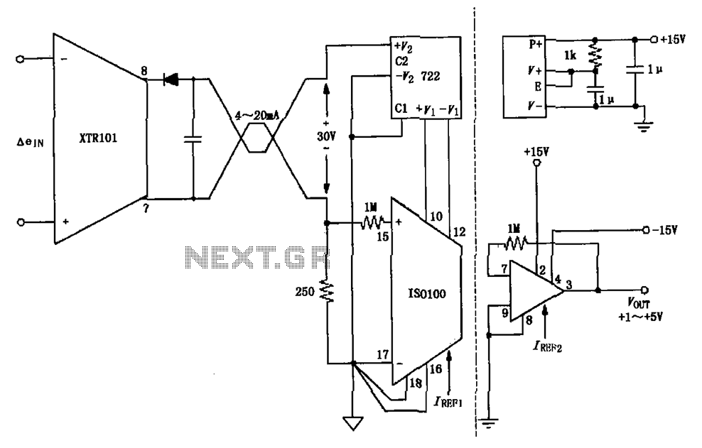
The circuit combines the XTR101 with the ISO100 isolation amplifier to transform a 4-20 mA current signal into a voltage output ranging from +1V to +5V while providing power supply isolation. It features excellent anti-jamming capabilities, making it suitable...
The WPG DM8168 DaVinci high-definition video System on Chip (SoC) offers multiple DVR/NVR surveillance solutions, utilizing the MT9M033 image sensor as a key component in safety monitoring systems. This solution is complemented by Conexant's line of multi-channel video surveillance...
This is a single alarm circuit. The circuit includes automatic exit and entry delays, a timed bell cut-off, and a system reset. It has provisions for normally open and normally closed inputs. The single alarm circuit is designed to provide...
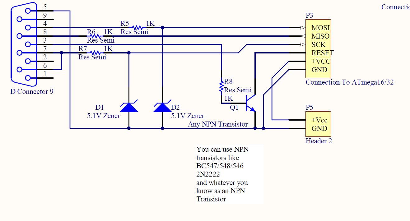
ISP programmer with circuit diagram for AVR Atmega32 microcontroller. This ISP burner circuit is an adaptation of the Pony programmer and uses PonyProg software. The ISP (In-System Programming) programmer designed for the AVR Atmega32 microcontroller facilitates the programming of the...
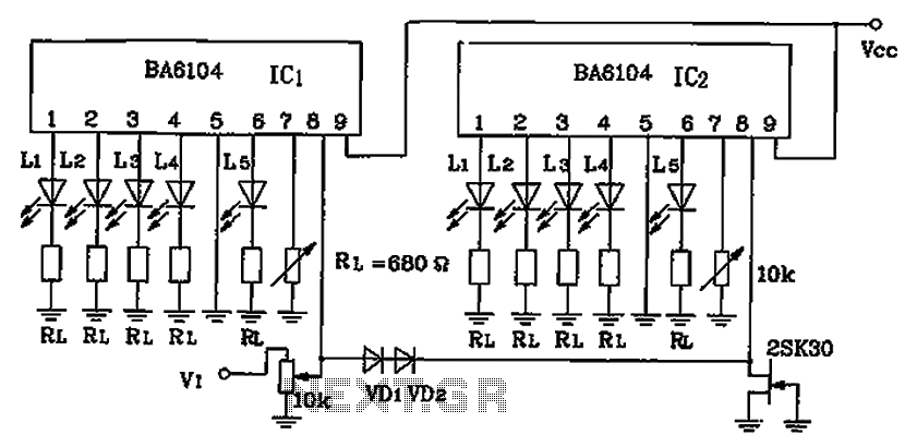
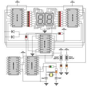
BA6104 is a five-digit LED level meter that functions as an LED display driver integrated circuit (IC). The configuration of the circuit is illustrated in the accompanying figure. The circuit utilizes a 10 by two-dot LED level display. The...
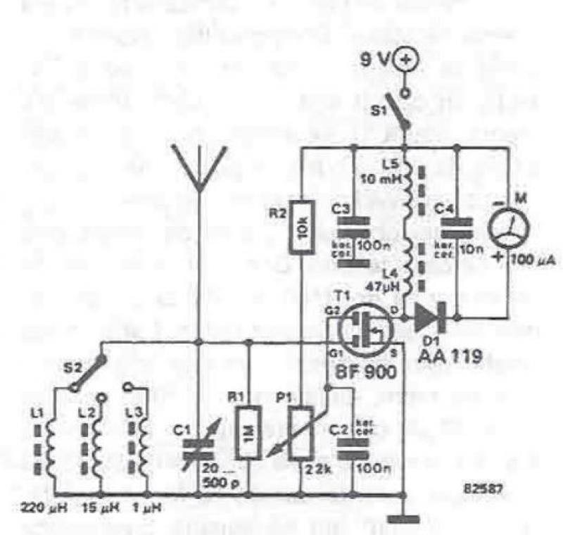
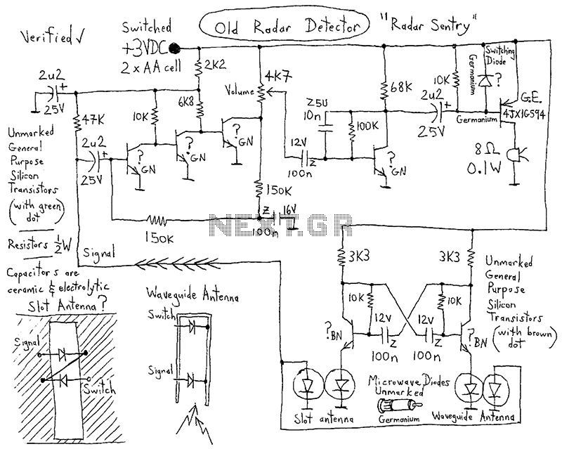
An RF field detector circuit suitable for measuring and verifying the power of antennas and transmitters can be constructed using transistors and common electronic components. This circuit employs a radio frequency transistor, specifically a MOS-FET with two gates. The...