
geiger power supply circuit
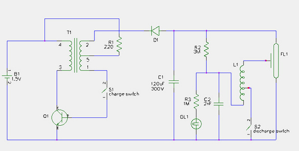
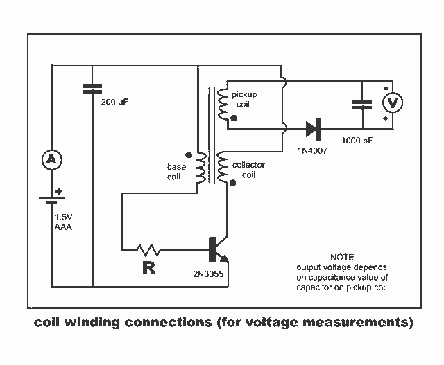
The modification of a disposable camera flash unit to power a Geiger tube involves several critical steps to ensure proper functionality and efficiency. Initially, the flash tube and trigger transformer must be carefully extracted from the circuit board. This requires a gentle approach to avoid damaging the surrounding components. The reflector assembly should be squeezed lightly to facilitate the removal of the flash tube and transformer.
Once these components are removed, the next step is to repurpose the capacitor from the trigger assembly. This capacitor acts as an output filter capacitor, which is essential for smoothing the voltage output to the Geiger tube. To integrate this capacitor into the circuit, it should be desoldered from its original position and repositioned across the traces connecting to the bulk capacitor. This can be achieved by rotating the capacitor and connecting it to the nearest hole that corresponds to the other leg of the previous output capacitor.
It is crucial to amend the schematic to reflect the absence of switch S1. Instead of a switch, a direct connection should be established from the potentiometer to the base of the transistor. This modification simplifies the circuit and allows for more straightforward control of the output voltage.
The potentiometer plays a vital role in adjusting the output voltage to the Geiger tube. The SBM20 model of the Geiger tube operates efficiently within a voltage range of 280V to 500V. Therefore, setting the output voltage to approximately 340VDC is advisable. This voltage level not only ensures the effective operation of the Geiger tube but also reduces the current drawn from the power supply batteries, thereby enhancing the overall efficiency of the circuit.
In summary, this modification requires careful handling of the components, precise soldering, and thoughtful adjustments to achieve the desired voltage output for the Geiger tube. Proper execution of these steps will result in a reliable power supply that utilizes the disposable camera flash unit effectively.This is a step by step guide to modifying the disposable camera flash unit that powers the Geiger tube in the last post. Geiger tube power supply hack using disposable camera flash unit Remove the flash tube and trigger transformer from the circuit board this can be done by gently squeezing the reflector assembly then pushing it carefully out of t
he circuit board Reuse the capacitor from the trigger assembly as a output filter capacitor. Remove it from the board and place it across the traces from the bulk capacitor. This can be done by simply rotating the capacitor across to the nearest hole that is connected to the other leg of where the output capacitor was. (see image) oops another mistake, the switch S1 that is in the schematic is no longer there, it should just be a connection from the potentiometer to the base of the transistor) Carefully adjust the potentiometer to get an output that will power your Geiger tube.
The Russian surplus SBM20 runs fine at 280-500V, so I chose to set my output to ~340VDC because at this level it draws less current from the batteries. 🔗 External reference
Related Circuits
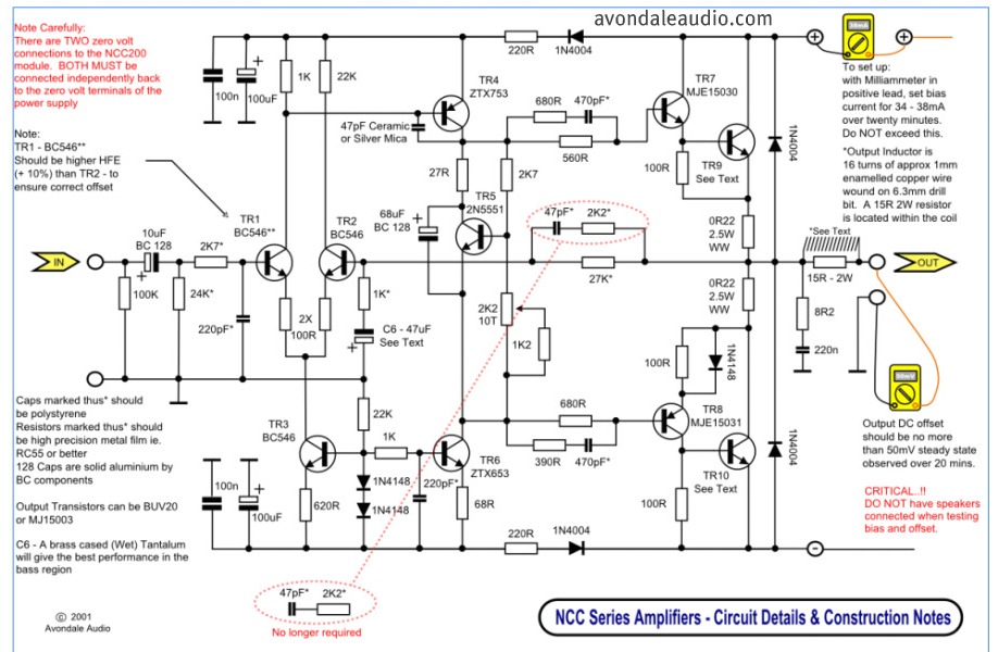
This is a simple circuit that features high-performance power amplifiers. The power amplifier is available as a PCB, along with a complete list of components. The described circuit utilizes high-performance power amplifiers, which are essential for applications requiring significant signal...
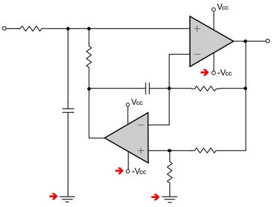
All filter stages utilizing a Virtual Ground will exhibit the Virtual Ground DC potential at their outputs, whereas all stages employing a resistive divider at their input (without a Virtual Ground) will present the divider potential at their output....
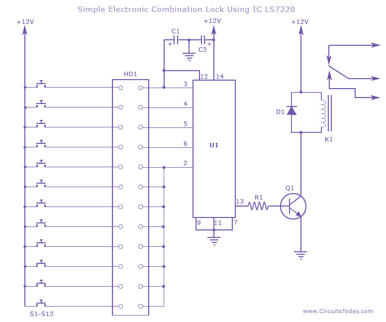
This circuit diagram illustrates a simple electronic combination lock utilizing the IC LS7220. It is designed to activate a relay for controlling any device (on & off) when a specific combination of four digits is entered. The circuit operates...
New Jewel Thief "Resonate LCR Circuit" with significantly reduced energy consumption. Measurements of voltage and current for the Joule thief. The Jewel Thief circuit, particularly the "Resonate LCR Circuit," is an innovative low-power design that enhances energy efficiency while maintaining...
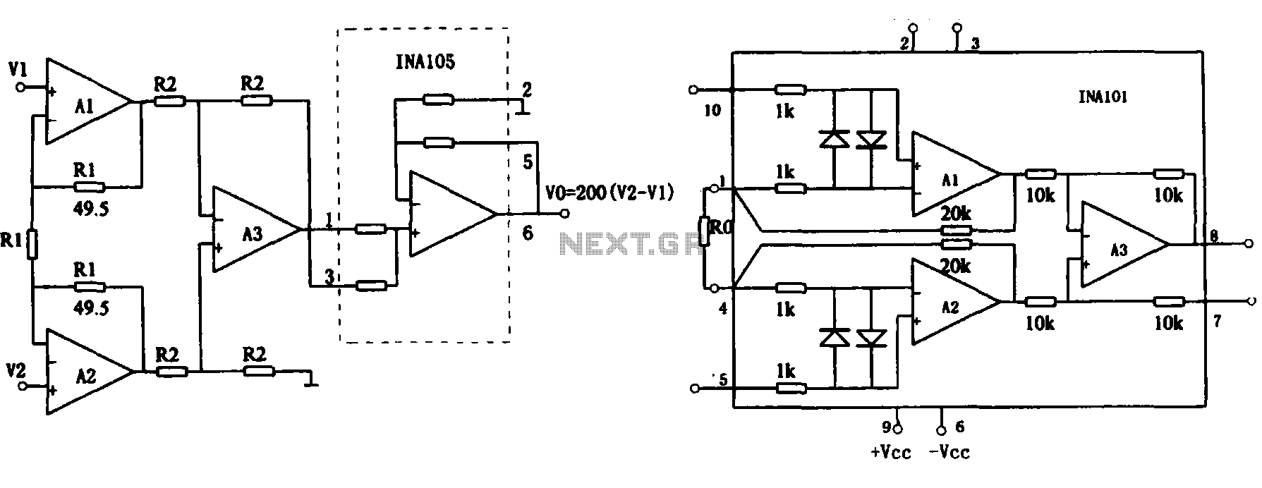
This document describes the extended common mode input voltage range of an instrument amplifier circuit. The circuit consists of three precision instrument amplifiers, A1, A2, and A3, which can be INA101 or INA102 models. The figure illustrates that A1,...

This is a low power voltmeter circuit designed for use with alternative energy systems that operate on 12V and 24V batteries. The voltmeter features an expanded scale that indicates small voltage steps within the 10 to 16 volt range...
Warning: include(partials/cookie-banner.php): Failed to open stream: Permission denied in /var/www/html/nextgr/view-circuit.php on line 713
Warning: include(): Failed opening 'partials/cookie-banner.php' for inclusion (include_path='.:/usr/share/php') in /var/www/html/nextgr/view-circuit.php on line 713