
Generator circuit
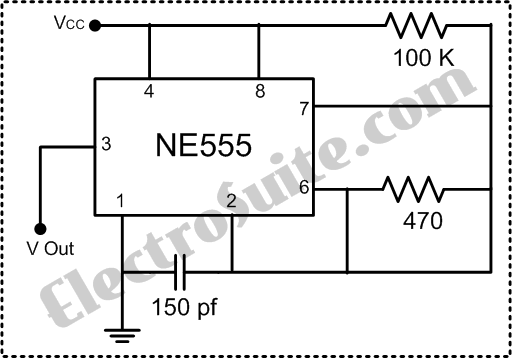
The circuit also includes a police siren generator using the popular 555 timer IC. The right 555 IC generates an alarm tone, while the left 555 IC operates as an astable multivibrator at 1 Hz. The output from the left 555 IC modulates the frequency of the right 555 IC, producing alternating frequencies of 440 Hz and 550 Hz at a 1 Hz rate. Additionally, a traffic light circuit using the 555 IC is designed for the UK, utilizing red, yellow, and green LEDs. This circuit is commonly used in electronics practice at schools and universities. The timing for the sequence of the red, yellow, and green lights varies from approximately 7 seconds to 2.5 minutes, adjustable via a 1M potentiometer. The astable 555 circuit provides clock pulses to a 4017 counter with ten outputs (Q0 to Q9), where each output goes high in succession upon receiving a pulse. The appropriate outputs are combined with diodes to drive the yellow and green LEDs, while the red LED is connected to output Q10, which is high during the first five counts (Q0-Q4), simplifying the circuit by reducing the number of diodes required.
The 555 timer's pin configuration allows it to generate clock signals for various applications, including digital clocks, LED decorations, 7-segment displays, metronomes in music, timers, and counters. With further adjustments, the 555 can also provide pulse width modulation (PWM) to control the frequency of high logic signals and set the desired duty cycle. Pin 5 (Control Voltage) alters the threshold and trigger voltage levels based on the rated voltage. The NE555 monolithic timing circuit serves as a stable time delay generator and can operate as an oscillator when configured with external resistors and capacitors. The circuit activates and resets on falling waveforms, providing an output capable of sourcing or sinking 200 mA, suitable for driving TTL circuits.
Additionally, an illumination intensity measurement system is described, where data is processed in digital form by a microprocessor. To convert analog signals into digital signals, an analog-to-digital converter (ADC0809) is utilized, converting analog voltage or current into a digital word. The digital output from the ADC is delivered via a printer port for further processing.The 60 Hz Frequency Generator circuit is very urgently needed to make the inverter or hardware related to the AC current voltage. This 60 Hz Frequency Generator is very simple and has a high accuration, the squarewave as the output which is precision.
The heart of this 60 Hz Frequency Generator is IC CD4060 as the IC Counter / Divider and also cou ld be adjusted for the oscillator function. This IC and the crystal as the tank circuit, with the range of supply power from +5Vdc until +9Vdc. The tank circuit is formed by R1, VC1 and Xtal. VC1 as the tuning to make the value of the pulse frequency to get the best 60 Hz Frequency Generator. Rangkaian ini adalah Sirine Mobil Polisi Negara Inggris dengan IC 555, di sini kita menggunakan IC yang paling populer di dunia, yaitu IC Clock Generator 555.
IC 555 yang berada di sebelah kanan berfungsi sebagai pembangkit nada alarm, dan IC 555 yang berada di sebelah kiri berfungsi sebagai Multivibrator Astable 1 Hz. Keluaran (output) pada IC 555 yang berada sebelah kiri adalah sebagai masukan untuk memodulasikan frekwensi terhadap IC 555 yang berada di sebelah kanan.
Hal ini menyebabkan sinyal frekwensi yang dihasilkan bergantian antara 440Hz dan 550Hz dengan rasio putaran sebesar 1Hz. Sekarang kita akan mencoba membuat Rangkaian Lampu Lalu lintas menggunakan IC 555 untuk di negara Inggris dengan menggunakan lampu LED berwarna Merah, Kuning dan Hijau, rangkaian ini banyak sekali dan umum dipakai di praktek elektronika di tiap-tiap sekolah atau kampus.
Waktu yang dibutuhkan untuk menyelesaikan secara berurutan untuk lampu warna Merah Merah dan Kuning Hijau Kuning adalah bervariasi dari sekitar 7 detik sampai 2, 5 menit dengan menyesuaikan pada komponen Potensiometer sebesar 1M. Rangkaian IC 555 astabil memberikan pulsa clock untuk counter 4017 yang mempunyai sepuluh output (Q0 sampai Q9).
Masing-masing output menjadi tinggi pada gilirannya saat pulsa di terima. Output yang tepat dikombinasikan dengan dioda untuk memasok kuning dan LED hijau. LED merah terhubung ke output 10 G· yang tinggi untuk menghitung pertama 5 (Q0-Q4 tinggi), ini menghemat menggunakan 5 dioda untuk merah dan menyederhanakan rangkaian. This is 555 IC Timer Pin Configuration, The function of IC555 to generate the clock signal or the signal box.
How our creativity to assemble, the function IC 555 can be used for multiple functions such as digital clock for clock, decoration using LED lights, turn on the 7-segment with astable circuit, metronome in the music industry, a timer counter, or with more tweaking longer able to provide a PWM (pulse width modulation) which regulates the frequency of the high logic signal to set the desired duty cycle. Pin 5 (Control Voltage). If the rated voltage, then the threshold voltage level will change from 2 / 3 Vcc to V5. Trigger voltage level will change from 2 / 3 Vcc to V5 This is Clock Function Generator NE555 Part 3 suite, NE555 monolithic timing circuit is a regulator that is capable of generating stable time delay or shocks that carefully.
There are additional terminals to ignition or reset. In the operating range of time delay, to operate as an oscillator is not stable, when driven carefully with 2 resistors and condensers extern. The circuit will be lit and reset on falling waveforms, and the composition of output will be a source or sink to 200mA or can drive TTL circuits.
This is Illumination Intensity Measurement System Diagram Part 1. The data in the microprocessor is always in digital form. This is different from the reality of the outside world, commonly known form of analog data. To convert analog signals into digital signals, it requires analog to digital conversion, and IC ADC0809 is a main component. This tool will do the conversion analog voltage or current conversion into a digital word. Digital word generated by the ADC (Analog to Digital Converter) delivered by the printer port that is then connected to the
🔗 External reference
Related Circuits
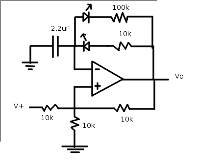
The relaxation oscillator generates a relatively consistent square wave. By altering the duty cycle, the effect can be visualized using LEDs. The following variation of the relaxation oscillator circuit can be assembled. The relaxation oscillator circuit typically consists of a...
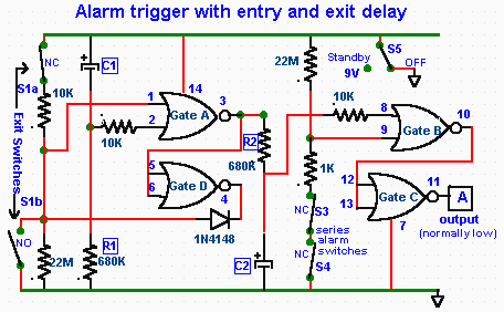
The CD4001 quad 2-input NOR gate is a highly versatile integrated circuit (IC) that can be utilized in numerous applications. This example demonstrates its use in a simple alarm system. The recommended power supply voltage for the CD4001 ranges...
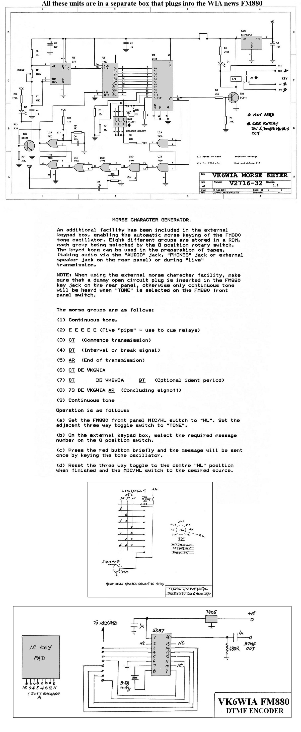
The unit is based on a PHILIPS FM880 link transceiver originally supplied to a Telecom Australia specification for telephone applications in remote areas of Australia. The FM880 is part of a family of equipment that includes the PHILIPS FM828/FM814...
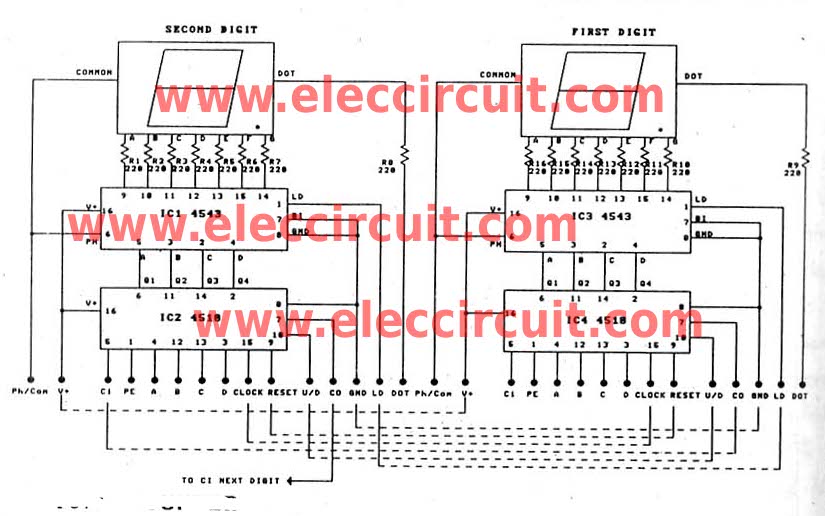
This is a versatile digital counter circuit that is cost-effective due to the basic components available in many electronic shops. The digital counter circuit is designed to count pulses and display the count on a digital readout, typically using a...
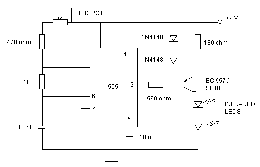
Just point this small device at the TV and the remote gets jammed. The circuit is self-explanatory. 555 is wired as an astable multivibrator for a frequency of nearly 38 kHz. This is the frequency at which most of...

This Outdoor LED Solar Garden Lights project is a hobby circuit for an automatic garden light that utilizes a light-dependent resistor (LDR) and a 6V/5W solar panel. During daytime, the internal rechargeable 6 Volt sealed lead-acid (SLA) battery is...