
GenesisRadio Transceivers
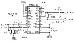
The construction of the circuit requires careful attention to detail, particularly during the assembly of the power supply stage. The 5 Volt rail is critical for the operation of CMOS ICs, which are sensitive to voltage variations. The use of a zener diode in conjunction with the regular diodes ensures voltage regulation and protection against reverse polarity, which can damage the sensitive components. The specification for the external power supply emphasizes the need for a robust source capable of maintaining stable voltage under load, which is essential for the reliable operation of the entire system.
In the assembly process, it is important to cross-reference the components with both the online and Word documentation to ensure all necessary parts are accounted for. The discrepancies in component identifiers between the schematics and the PCB silkscreen can lead to confusion; therefore, a meticulous approach is recommended. The virtual build method serves as an effective strategy to visualize the assembly process, allowing for identification of potential issues before physical assembly begins.
Overall, thorough preparation and understanding of the circuit design, along with careful assembly practices, will contribute significantly to the successful completion of the project. The integration of feedback from the assembly process and the request for improved documentation will enhance future iterations of the kit and support more efficient troubleshooting and assembly for users.Later, I will use the same pivot table to list the parts out by each of the 8 phases in the build, organizing them into phase-specific bags O` parts. First thing I notice is that there are some slight disconnects between the liberally illustrated, online assembly pictorials (with associated instructions) and the Word Document of the Assembly Manual.
For example, Phase 1 calls for 21 diodes plus a zener diode. These are referenced in the online docs, but not in the word document. My customary practice of breaking the schematic out by phase is likely not going to work for me with this kit. Still, everything is all there; just spread out a bit. Lesson to be taken away from this is to thoroughly review the instructions (all versions: Word, on-line, and BOM) for each phase before beginning construction in that phase.
You want to know what you are doing with each component and where on the board! Before going into a build, I always like to familiarize myself with the schematics and make sure I can track from the schematic to the PCB and vice versa. The documentation provided on the website ( Word Document ) has 4 bits of schematic which are apparently snapshots of development as the design progressed (or intended for general purpose use in the follow-on kits).
Unfortunately, at least for me, this made it quite difficult to track from the schematic to the PC and back, since the identifiers (e. g. , "R9", "C53", "L4", etc. ) of most of the components in the schematics did not match with the identifiers on the silk-screen. Of course, one could always reverse engineer the PCB back to the schematic by essentially repeating the schematic-to-pcb mapping process in reverse.
I am not up to that task and have asked GenesisRadio if it might be possible to publish a complete schematic that agrees on component identifiers with the pcb silkscreen. This would make any required troubleshooting (not that I expect to need any) infinitely easier. When I encounter a new kit and a new design, I like to go through a "virtual build" - virtually placing components onto an image of the board, stage-by-stage.
This forces me to devote the time and effort to really understand the circuit(s) and also provides materials for use in enhanced documentation of the kit and its construction. This turns out to be particularly valueable in the case of the G40 because there are potential ambiguities brought about by the schematic segmentation and inconsistent component identification mentioned above.
The purpose of this stage is to provide the 5 Volt power rail for the CMOS ICs (as well as provide for Power and TX LEDs and the 12 Volt input point. Make sure your external power supply has the correct volatge (12-13. 8 Vdc) and it should be capable of producing 2 to 3 Amps. A faulty or underrated power supply is a very common problem. This stage had two areas of the board which were populated to provide the 5 V power supply and the LEDs for RX and TX.
In addition, there were some diodes that were populated throughout the board (1 zener and 21 regular diodes). Parts of this stage are spread across two of the schematics: "Genesis G* RX/TX PC Control + CW Monitor Design" and "Monoband HF SDR Transceiver Genesis G40".
🔗 External reference
Related Circuits
An article previously discussed connecting to the Raspberry Pi board from a Linux PC using the serial port. This time, the focus is on how to achieve the same connection using a Windows PC. In this case, a Windows...

The relay power in the linear circuit is derived from a -120 V bias supply, while the transmit keying output from the Kenwood device is +12 V with a maximum current of 10 mA. A critical component of this...
The original firmware is functional on amateur radio bands; however, it lacks user-friendliness. Wulf-Gerd, DL1FAC, has developed a new firmware that is significantly more suitable for amateur radio users. This firmware is open source, allowing for flexible frequency adjustments,...
Warning: include(partials/cookie-banner.php): Failed to open stream: Permission denied in /var/www/html/nextgr/view-circuit.php on line 713
Warning: include(): Failed opening 'partials/cookie-banner.php' for inclusion (include_path='.:/usr/share/php') in /var/www/html/nextgr/view-circuit.php on line 713