
getting started with arduino chapter seven
The context of using Arduino microcontrollers in real-time applications opens diverse project possibilities. Understanding numerical systems such as binary, BCD, and hexadecimal is crucial for programming and interfacing with various components. The BCD representation is particularly significant when dealing with time-related integrated circuits, as it allows for accurate data interpretation and manipulation.
The switch-case structure enhances code readability and efficiency when making decisions based on variable values. This is especially useful in complex applications where multiple conditions must be evaluated. The example provided illustrates how to implement this function effectively, promoting cleaner and more maintainable code.
Furthermore, the I2C bus interface is a vital aspect of modern electronics, enabling seamless communication between multiple devices. The two-wire setup minimizes wiring complexity while allowing for robust data exchange. In practical applications, this means that the Arduino can easily control and communicate with various peripherals, including sensors and timing devices, through this standardized protocol.
By mastering these concepts, users can leverage the full potential of Arduino microcontrollers to create innovative and effective electronic solutions that utilize real-time data processing and control mechanisms. Understanding these foundational elements is essential for anyone aiming to develop advanced projects in the realm of embedded systems and automation.This is part of a series titled Getting Started with Arduino!Atutorial on the Arduino microcontrollers. The first chapter is here, the complete index is here. This week is going to focus around the concept of real time, and how we can work with time to our advantage.
(Perhaps working with time to our disadvantage is an oxymoron ) On ce we have the ability to use time in our sketches, a whole new world of ideas and projects become possible. From a simple alarm clock, to complex timing automation systems, it can all be done with our Arduino and some brainpower.
There is no time to waste, so let`s go! First of all, there are a few mathematical and variable-type concepts to grasp in order to be able to understand the sketch requirements. It is a bit dry, but I will try and minimise it. Can you recall from chapter four how binary numbers worked If not, have a look then come back. Binary coded decimal (or BCD) numbers are similar, but different each digit is stored in a nibble of data.
Remember when working with the 74HC595 shift registers, we sent bytes of data a nibble is half of a byte. For example: However, remember each digit is one nibble, so to express larger numbers, you need more bits.
For example, 12 would be 0001 0010; 256 is 0010 0101 0110, etc. Note that two BCD digits make up a byte. For example, the number 56 in BCD is 0101 0110, which is 2 x 4 bits = 1 byte. Anyhow, moving forward we now take a look at hexadecimal numbers. Hex` numbers are base-16, in that 16 digits/characters are used to represent numbers. Can you detect a pattern with the base-x numbers Binary numbers are base-2, as they use 0 and 1; decimal numbers are base-10, as they use 0 to 9 and hexadecimal numbers use 0 to 9 then A to F. Run the following sketch to see how they compare with binary and decimal. Unfortunately the IC we use for timing uses BCD, so we need to be able to convert to and from BCD to make sense of the timing data.
So now we have an understanding of BCD, binary, base-10 decimal, bytes, hexadecimal and nibbles. What a mouthful that was! Before we head back to timing, let`s look at a new function: switch case. Say you needed to examine a variable, and make a decision based on the value of that variable, but there were more than two possible options. You could always use multiple if then else if functions, but that can be hard on the eyes. That is where switch case comes in. It is quite self-explanatory, look at this example: switch (zz) { case 10: //do something when variable zz equals 10 break; case 20: //do something when variable zz equals 20 break; case 30: // do something when variable equals 30 break; default: // if nothing else matches, do the default // default is optional } OK, we`re back.
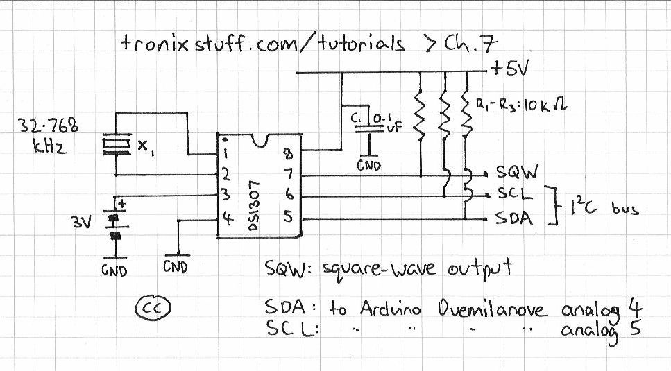
It would seem that this chapter is all numbers and what not, but we are scaffolding our learning to be able to work with an integrated circuit that deals with the time for us. There is one last thing to look at then we can get on with timing things. And that thing is (There are two ways one could explain this, the simple way, and the detailed way. As this is Getting Started with Arduino , I will use the simple method. If you would like more detailed technical information, please read this document: NXP I2C Bus. pdf, or read the detailed website by NXP here ) The I2C bus (also known as two wire interface ) is the name of a type of interface between devices (integrated circuits) that allows them to communicate, control and share data with each other.
(It was invented by Philips in the late 1970s. [ Philips spun off their semiconductor division into NXP ]). This interchange of data occurs serially, using only two wires (ergo two wire interface), one called SDA (serial data) and the other SCL (serial clock). A device can be a master, or a slave. In our situation, the Arduino is the master, and our time chip is the slave. Each chip on the bus has their own unique address , 🔗 External reference
Related Circuits
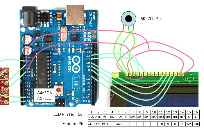
For an effective tutorial on connecting a standard LCD to an Arduino and utilizing the standard LCD library, refer to the LadyAda Tutorial on LCDs. The diagram illustrates the fundamental connections with a standard LCD that is compatible with...
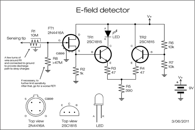
A JFET is employed to detect the electric field generated by high voltage power lines. The JFET amplifies the signal minimally but reduces the impedance and supplies current at a level appropriate for transistor amplification. The two transistors can...
A straightforward project involves using an Arduino to rotate a GH-2 camera on a fluid head by specified degrees to capture 360-degree panoramas. The motor control is uncomplicated, and there is a wealth of DIY motor projects available. Assistance...
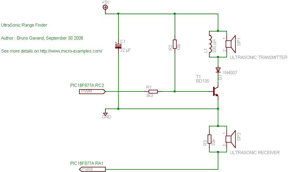
A cat deterrent system utilizing an Arduino, similar to existing models. Detection has been successfully implemented, and it has been determined that an ultrasonic transducer is required to generate the necessary deterrent sound. The proposed cat deterrent system employs an...
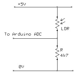
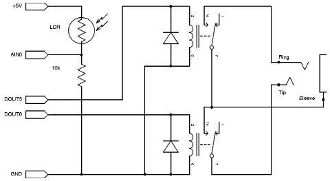
A Light Dependent Resistor (LDR) is utilized to create a simple nightlight for children's bedrooms that automatically turns on in darkness and off in light. The resistance of an LDR varies based on the light intensity it receives. In...
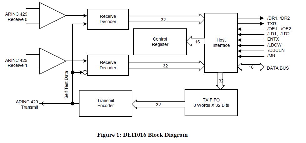
This document outlines the process of interfacing an Arduino with an ARINC 429 transceiver, illustrating the general methodology for connecting an Arduino to electronic circuits that can be applied to individual designs. The ARINC 429 bus is the predominant...
Warning: include(partials/cookie-banner.php): Failed to open stream: Permission denied in /var/www/html/nextgr/view-circuit.php on line 713
Warning: include(): Failed opening 'partials/cookie-banner.php' for inclusion (include_path='.:/usr/share/php') in /var/www/html/nextgr/view-circuit.php on line 713