
ghrobotics
For this experiment, a light-dependent resistor (LDR) was utilized to control the speed of a DC motor through a voltage divider configuration. The LDR was connected in series with a resistor, and the output was taken from the center point of this configuration. This output was then fed into analog channel 1 of the microprocessor, which was used in the code to determine the duration of the on and off periods for the LATD bits that drive the motor chip. The PIC kit 2 and the microprocessor used in the laboratory work for robotics were also referenced. Key connections between the PIC kit and the microprocessor include: Pin 1 of the PIC kit connecting to Pin 1 of the microprocessor for memory reset, Pin 2 to Pin 11 for a positive 5V supply, Pin 3 to Pin 12 for a 0V reference, and Pins 4 and 5 to Pins 25 and 26 of the microprocessor for signal connections. Additional connections between the microprocessor and the driver chip are established from the PWM pins or the LAT bits of the microprocessor to the signal inputs on the driver chip, enabling control of the motor connected to the driver chip through programs stored in the microprocessor. In this experiment, the driver chip was used to control a stepper motor, which was connected across both sides of the driver chip with the center tap connected to 0V. This configuration provided a small degree of control over the stepper motor.
The L293D quad half H-bridge integrated circuit (IC) motor driver was employed to interface the microprocessor with the stepper motor. The L293D is designed to control the direction and speed of DC motors and stepper motors by allowing the microprocessor to send control signals that dictate the operation of the motor. The connections between the microprocessor and the L293D include the output pins from the microprocessor's LATD register, which are mapped to the input pins of the L293D, enabling the microprocessor to control the H-bridge circuitry.
The microprocessor's analog input channel is used to read the voltage output from the voltage divider formed by the LDR and the resistor. This voltage is proportional to the light intensity detected by the LDR, allowing for dynamic control of the motor speed based on ambient light conditions. The software running on the microprocessor continuously reads this analog value and adjusts the delay between the on and off states of the LATD bits, thereby controlling the stepper motor's speed.
In the code provided, the configuration of the pins is crucial for proper operation. The analog inputs are set up to allow for voltage readings from the LDR, while the digital outputs are configured to control the motor through the L293D. The PWM settings are also established to enable precise control over the motor's speed and direction.
The stepper motor's operation is managed by a simple while loop that sequentially activates each LATD bit, creating a stepping motion. This method of control allows for smooth operation and accurate positioning of the stepper motor, which is essential in robotic applications where precise movement is required. The combination of the LDR for sensing light and the L293D for motor control exemplifies an effective integration of analog and digital components in an embedded system.For this experiment I used a light dependant resistor (LDR) to control the speed of a DC motor. I achieved this by means of a voltage divider. I connected in series a resistor and the LDR and used the centre point of this as my output. This output was then inputted into analog channel1 of the microprocessor. This input was then used within my code to determine the length of the delay for the on and off period of the LATD bits driving the motor chip. The images above are of the Pic kit 2 and the micro processor used throughout thelab work for robotics.
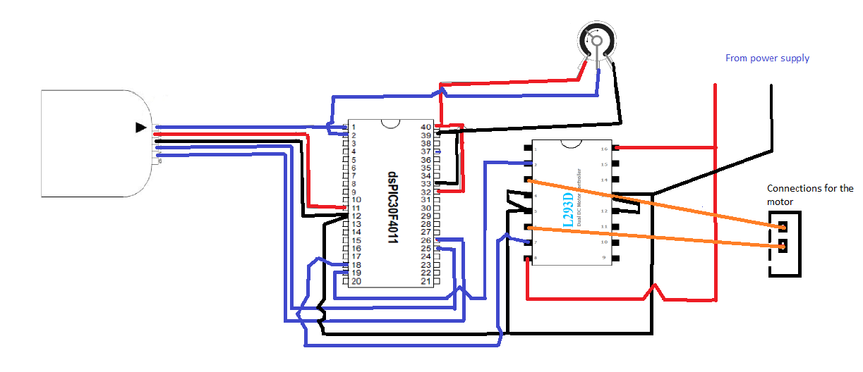
There are some basic connections I want to point out between the two. Pin 1on the pic kit goes to pin 1 on the micro processor(MP), this allows the pic kit to reset the memory on the micro processor(MP). The 2nd pin on the pic kit goes to pin number 11 on the MP, this is a posistive 5volts supply for the MP to operate.
The 3rd pin on the pic kit goes to the 12th pin on the MP this is the0volts reference point. The 4th and 5th pins from the pic kit go out to the 25th and 26th pins of the MP respectively, these are signal connections between the two devices. There are which are not shown here between the MP and the driver chip which are from either the PWM pins or the LAT bits of the MP to the signal inputs on the driver chip.
This allows for control of whatever motor is connected to the driver chip by programs stored in the MP. In this experiment I have used the driver chip to control the steppermotor. The stepper motor is connected across both sides of the driverchip and the centre tapping points are connected to 0volts.
This setup for the stepper motor gives me a small degree // // Written by Graham Hogan - 10/11/11 // #include #include // Configuration settings _FOSC(CSW_FSCM_OFF & FRC_PLL16); // Fosc=16x7. 5MHz, Fcy=30MHz _FWDT(WDT_OFF); // Watchdog timer off _FBORPOR(MCLR_DIS); // Disable reset pin // Function prototypes void configure_pins(); unsigned int read_analog_channel(int n); int main() { int voltage; // Set up which pins are which configure_pins(); //While loop turns on and off the LATD bits from 0 to 3 one at a time in sequence and causes the motor to rotate while(1) { _LATD0 = 1; _delay32(35000); _LATD0 = 0; _LATD1 = 1; _delay32(35000); _LATD1 = 0; _LATD2 = 1; _delay32(35000); _LATD2 = 0; _LATD3 = 1; _delay32(35000); _LATD3 = 0; } return 0; } void configure_pins() { // Configure RD0 as a digital output LATD = 0; TRISD = 0b11110000; // Configure analog inputs TRISB = 0x01FF; // Port B all inputs ADPCFG = 0xFF00; // Lowest 8 PORTB pins are analog inputs ADCON1 = 0; // Manually clear SAMP to end sampling, start conversion ADCON2 = 0; // Voltage reference from AVDD and AVSS ADCON3 = 0x0005; // Manual Sample, ADCS=5 -> Tad = 3*Tcy = 0.
1us ADCON1bits. ADON = 1; // Turn ADC ON // Configure PWM for free running mode // PWM period = Tcy * prescale * PTPER = 0. 33ns * 64 * 9470 = 20ms PWMCON1 = 0x00FF; // Enable all PWM pairs in complementary mode PTCON = 0; _PTCKPS = 3; // prescale=1:64 (0=1:1, 1=1:4, 2=1:16, 3=1:64) PTPER = 9470; // 20ms PWM period (15-bit period value) PDC1 = 0; // 0% duty cycle on channel 1 (max is 65536) PDC2 = 0; // 0% duty cycle on channel 2 (max is 65536) PDC3 = 0; // 0% duty cycle on channel 3 (max is 65536) PTMR = 0; // Clear 15-bit PWM timer counter _PTEN = 1; // Enable PWM time base } // This function reads a single sample from the specified // analog input.
It should take less than 2. 5us if the chip // is running at about 30 MIPS. unsigned int read_analog_channel(int channel) { ADCHS = channel; // Select the requested channel ADCON1bits. SAMP = 1; // start sampling _delay32(30); // 1us delay @ 30 MIPS ADCON1bits. SAMP = 0; // start Converting while (!ADCON1bits. DONE); // Should take 12 * Tad = 1. 2us return ADCBUF0; } For this experiment a L293D quad half H-bridge IC motor driver chip was connected to the PIC.
I took a power supply from the microproces 🔗 External reference
The L293D quad half H-bridge integrated circuit (IC) motor driver was employed to interface the microprocessor with the stepper motor. The L293D is designed to control the direction and speed of DC motors and stepper motors by allowing the microprocessor to send control signals that dictate the operation of the motor. The connections between the microprocessor and the L293D include the output pins from the microprocessor's LATD register, which are mapped to the input pins of the L293D, enabling the microprocessor to control the H-bridge circuitry.
The microprocessor's analog input channel is used to read the voltage output from the voltage divider formed by the LDR and the resistor. This voltage is proportional to the light intensity detected by the LDR, allowing for dynamic control of the motor speed based on ambient light conditions. The software running on the microprocessor continuously reads this analog value and adjusts the delay between the on and off states of the LATD bits, thereby controlling the stepper motor's speed.
In the code provided, the configuration of the pins is crucial for proper operation. The analog inputs are set up to allow for voltage readings from the LDR, while the digital outputs are configured to control the motor through the L293D. The PWM settings are also established to enable precise control over the motor's speed and direction.
The stepper motor's operation is managed by a simple while loop that sequentially activates each LATD bit, creating a stepping motion. This method of control allows for smooth operation and accurate positioning of the stepper motor, which is essential in robotic applications where precise movement is required. The combination of the LDR for sensing light and the L293D for motor control exemplifies an effective integration of analog and digital components in an embedded system.For this experiment I used a light dependant resistor (LDR) to control the speed of a DC motor. I achieved this by means of a voltage divider. I connected in series a resistor and the LDR and used the centre point of this as my output. This output was then inputted into analog channel1 of the microprocessor. This input was then used within my code to determine the length of the delay for the on and off period of the LATD bits driving the motor chip. The images above are of the Pic kit 2 and the micro processor used throughout thelab work for robotics.
There are some basic connections I want to point out between the two. Pin 1on the pic kit goes to pin 1 on the micro processor(MP), this allows the pic kit to reset the memory on the micro processor(MP). The 2nd pin on the pic kit goes to pin number 11 on the MP, this is a posistive 5volts supply for the MP to operate.
The 3rd pin on the pic kit goes to the 12th pin on the MP this is the0volts reference point. The 4th and 5th pins from the pic kit go out to the 25th and 26th pins of the MP respectively, these are signal connections between the two devices. There are which are not shown here between the MP and the driver chip which are from either the PWM pins or the LAT bits of the MP to the signal inputs on the driver chip.
This allows for control of whatever motor is connected to the driver chip by programs stored in the MP. In this experiment I have used the driver chip to control the steppermotor. The stepper motor is connected across both sides of the driverchip and the centre tapping points are connected to 0volts.
This setup for the stepper motor gives me a small degree // // Written by Graham Hogan - 10/11/11 // #include
1us ADCON1bits. ADON = 1; // Turn ADC ON // Configure PWM for free running mode // PWM period = Tcy * prescale * PTPER = 0. 33ns * 64 * 9470 = 20ms PWMCON1 = 0x00FF; // Enable all PWM pairs in complementary mode PTCON = 0; _PTCKPS = 3; // prescale=1:64 (0=1:1, 1=1:4, 2=1:16, 3=1:64) PTPER = 9470; // 20ms PWM period (15-bit period value) PDC1 = 0; // 0% duty cycle on channel 1 (max is 65536) PDC2 = 0; // 0% duty cycle on channel 2 (max is 65536) PDC3 = 0; // 0% duty cycle on channel 3 (max is 65536) PTMR = 0; // Clear 15-bit PWM timer counter _PTEN = 1; // Enable PWM time base } // This function reads a single sample from the specified // analog input.
It should take less than 2. 5us if the chip // is running at about 30 MIPS. unsigned int read_analog_channel(int channel) { ADCHS = channel; // Select the requested channel ADCON1bits. SAMP = 1; // start sampling _delay32(30); // 1us delay @ 30 MIPS ADCON1bits. SAMP = 0; // start Converting while (!ADCON1bits. DONE); // Should take 12 * Tad = 1. 2us return ADCBUF0; } For this experiment a L293D quad half H-bridge IC motor driver chip was connected to the PIC.
I took a power supply from the microproces 🔗 External reference