
Glitch-free-turbo-circuit
This circuit generates a dual-speed clock for personal computers. It synchronizes asynchronous switch inputs with the master clock to provide glitch-free transitions between clock speeds. The dual-speed clock allows certain programs to operate at a higher clock speed for faster execution, while other programs, such as those using loops for timing, can run at a lower speed when necessary. The circuit is compatible with any master clock frequency that meets the minimum pulse width specifications of the flip-flops. The configuration includes two D flip-flops, IC1 and IC2, along with an XOR gate, IC3, which together form a binary divider that produces 6 MHz and 12 MHz clock signals. When the NT signal is low, the reset pin forces the 6 MHz output to a low state. Conversely, when the NT signal is high, IC3 blocks the 12 MHz output. Consequently, only one of the two clock signals is passed through IC3 and subsequently clocked into IC6. The master clock signal also clocks IC6, ensuring that asynchronous switching of the NT signal does not generate an output pulse shorter than 41 microseconds (1/24 MHz), thereby eliminating glitches.
The dual-speed clock circuit is designed to enhance the performance of personal computers by providing flexibility in clock speeds. The use of two D flip-flops, IC1 and IC2, serves to create a binary division of the master clock frequency. This division allows for the generation of two distinct clock frequencies, specifically 6 MHz and 12 MHz, which are essential for accommodating different types of software requirements. The XOR gate, IC3, plays a critical role in controlling the output of these clock signals based on the state of the NT signal.
In operation, when the NT signal is low, the reset functionality ensures that the 6 MHz clock output is disabled, preventing any undesired signals from propagating through the circuit. This mechanism is crucial for maintaining the integrity of the clock signals. When the NT signal transitions to a high state, IC3 selectively allows the 12 MHz clock output to pass through, thereby enabling higher-speed operations when required.
The synchronization aspect of this circuit is vital for ensuring that transitions between clock speeds occur without glitches. Glitches can cause erratic behavior in digital circuits, particularly in timing-critical applications. By employing a master clock signal to clock IC6, the circuit guarantees that any changes in the NT signal do not lead to output pulses shorter than the specified minimum duration. This design consideration effectively mitigates the risk of glitches, ensuring stable and reliable operation across different clock speeds.
Overall, this dual-speed clock circuit is an effective solution for optimizing the performance of personal computers, allowing for dynamic adjustment of clock frequencies based on the operational requirements of various software applications.This simple circuit generates a dual-speed clock for personal computers. The circuit synchronizes your asynchronous switch inputs with the master clock to provide glitch-free transitions from one clock speed to the other. The dual-speed clock allows some programs to run at the higher clock speed in order to execute more quickly.
Other programs- for example, programs that use loops for timing-can still run at the lower speed as necessary. The circuit will work with any master-clock frequency that meets the flip-flops minimumpulse- width specs.
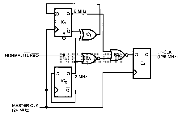
The two D two flip-flops, JC1 and IC2, and an XOR gate, IC3, form a binary divider that develops the 6- and 12-MHz clocks. When the NT signal is low, the reset pin forces the 6cMHz output low. On the other hand, when the NT signal is high, JC3 blocks the 12-MHz output. Therefore, only one of the two clock signals passes through JC3 and gets clocked into IC6. Because the master-elk signal clocks IC6, asynchronous switching of the NT signal can"t generate an output pulse shorter than 41 p.s (1/24 MHz).
Also, the synchronization eliminates glitches. 🔗 External reference
The dual-speed clock circuit is designed to enhance the performance of personal computers by providing flexibility in clock speeds. The use of two D flip-flops, IC1 and IC2, serves to create a binary division of the master clock frequency. This division allows for the generation of two distinct clock frequencies, specifically 6 MHz and 12 MHz, which are essential for accommodating different types of software requirements. The XOR gate, IC3, plays a critical role in controlling the output of these clock signals based on the state of the NT signal.
In operation, when the NT signal is low, the reset functionality ensures that the 6 MHz clock output is disabled, preventing any undesired signals from propagating through the circuit. This mechanism is crucial for maintaining the integrity of the clock signals. When the NT signal transitions to a high state, IC3 selectively allows the 12 MHz clock output to pass through, thereby enabling higher-speed operations when required.
The synchronization aspect of this circuit is vital for ensuring that transitions between clock speeds occur without glitches. Glitches can cause erratic behavior in digital circuits, particularly in timing-critical applications. By employing a master clock signal to clock IC6, the circuit guarantees that any changes in the NT signal do not lead to output pulses shorter than the specified minimum duration. This design consideration effectively mitigates the risk of glitches, ensuring stable and reliable operation across different clock speeds.
Overall, this dual-speed clock circuit is an effective solution for optimizing the performance of personal computers, allowing for dynamic adjustment of clock frequencies based on the operational requirements of various software applications.This simple circuit generates a dual-speed clock for personal computers. The circuit synchronizes your asynchronous switch inputs with the master clock to provide glitch-free transitions from one clock speed to the other. The dual-speed clock allows some programs to run at the higher clock speed in order to execute more quickly.
Other programs- for example, programs that use loops for timing-can still run at the lower speed as necessary. The circuit will work with any master-clock frequency that meets the flip-flops minimumpulse- width specs.
The two D two flip-flops, JC1 and IC2, and an XOR gate, IC3, form a binary divider that develops the 6- and 12-MHz clocks. When the NT signal is low, the reset pin forces the 6cMHz output low. On the other hand, when the NT signal is high, JC3 blocks the 12-MHz output. Therefore, only one of the two clock signals passes through JC3 and gets clocked into IC6. Because the master-elk signal clocks IC6, asynchronous switching of the NT signal can"t generate an output pulse shorter than 41 p.s (1/24 MHz).
Also, the synchronization eliminates glitches. 🔗 External reference