
Greenhouse Heater Temperature Control Project
The circuit design utilizes four 1N4148 diodes to enhance signal clarity for temperature sensing applications. This configuration is particularly beneficial in environments where precise temperature control is critical, such as HVAC systems. The thermal anticipation resistor, R1, plays a crucial role in minimizing temperature fluctuations by introducing a slight heating effect to the sensing device, thus enhancing the stability of the system.
The operational amplifier LM324 is employed due to its cost-effectiveness and adequate performance for this application. The design ensures that the diodes are properly biased, allowing for a consistent current flow that enhances the accuracy of the temperature readings. The voltage comparator configuration of U1C, complemented by positive feedback, ensures reliable switching behavior of the relay, which is essential for controlling heating elements in response to temperature changes.
The use of a calibration potentiometer (R8) allows for precise adjustments to the set point, ensuring that the system can be fine-tuned to meet specific operational requirements. The inclusion of a noise filter capacitor (C3) is also a significant design consideration, as it helps to mitigate any potential interference that could affect the performance of the temperature sensing circuit.
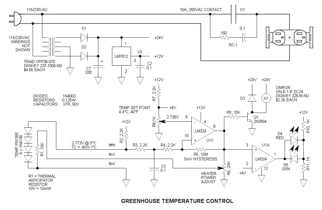
Overall, this circuit exemplifies a well-thought-out approach to temperature control in HVAC systems, balancing cost, performance, and reliability. The choice of components and configuration aims to provide a robust solution that can adapt to varying environmental conditions while maintaining efficient operation.This is simply (4) 1N4148 diodes connected in series with a thermal anticipation resistor (R1) heat shrunk together at the end of a (3) wire signal cable ”it is visible on some of the photos. The use of a thermal anticipation resistor is an old HVAC thermostat technique that adds negative feedback to the system by immediately heating the temperat
ure sensing device slightly. It forces short cycles and prevents temperature overshoot. Because the amount of power to apply to the thermal anticipation resistor was unknown, I incorporated a power level pot (R6). I later determined that it works quite well at the maximum setting, so the pot is not required. Although the temperature measurement can be accomplished via a single diode, four diodes in series are used to get the signal out of the mud.
The inexpensive LM324 op amp has a maximum input offset voltage of 7mV, so the higher level voltage signal helps to improve performance. The diodes are biased at approx 4mA via R2. U1C is connected as a voltage comparator with positive feedback via R5. Positive feedback prevents relay chatter. C3 is an input noise filter capacitor. As the temperature cools, the voltage drop across the probe diodes increases. When it reaches the set point, the output changes states and the positive feedback through R5 further increases the non-inverting input by 5mV to assure that it remains latched until the temperature increases and the voltage drops below the set point.
In a previous circuit we see that the temperature coefficient of silicon diodes is approx. -2mV / °C. (4) in series boosts it to -8mV / °C. I dropped the probe in ice water and measured the voltage ”2. 773V in my case. Then I calculated what the voltage would be at 4. 4 °C (40 °F). Then I adjusted the voltage at the calibration pot R8 to get 2. 738V ”this is the set point. Proper operation was subsequently determined by placing the probe in and out of ice water to observe cycling of the relay. Quencharc RC-1 is connected across the relay contacts to reduce arcing. These are unreasonably expensive, so I recommend using a discrete resistor and capacitor. Polypropylene is the capacitor of choice ”just make sure that it has sufficient AC voltage rating; The heater is a DIY rack of surplus power resistors that work out to 500W @ 115VAC ”very rugged, large and ugly Any resistance heater may be used.
I recommend one that has a low power setting as most run 1500 to 1800W. Surprisingly, the increase in my energy bill has not been noticeable. The last two years have not been cold, but this year seems more seasonable. As a result, I may have to use a larger heater ”at least during 10 °F and below temperatures. 🔗 External reference
Related Circuits
The simplest solution for implementing joystick control for a robot is to program the actions in software on a microcontroller. However, many users prefer off-the-shelf components, thus this circuit is designed using diodes, resistors, transistors, and a FAN8200 motor...
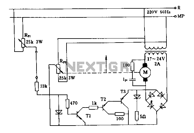
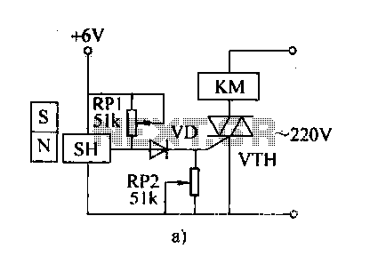
The FIG potentiometer RP2 has a sliding contact that is directly connected to the antenna. The system operates such that only when potentiometers RP1 and RP2 are positioned identically, do the non-conductive transistors and rectifier bridge remain off, resulting...
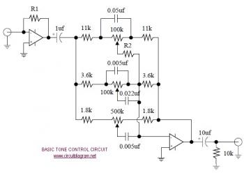
The following diagram illustrates the schematic of an Active Tone Control circuit, commonly referred to as "ACTOR." The ACTOR is an electronic audio circuit designed to enhance loudness by adjusting bass and treble audio signals. It operates using the...
The automatic weapon features a magnetic switch circuit that is simple, reliable, has a low failure rate, and offers good versatility. It can be used for output performance or converted into mechanical displacement applications. The circuit diagram utilizes a...
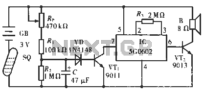
The circuit operates in such a way that when the patient is typically in an upright position, the SQ mercury switch is turned off, resulting in the alarm circuit being inactive. When the patient lies down, the SQ switch...
The circuit diagram below illustrates a schematic designed to control the speed of a low-power induction motor, commonly found in fans. The schematic for controlling the speed of a low-power induction motor typically incorporates several key components that work together...
Warning: include(partials/cookie-banner.php): Failed to open stream: Permission denied in /var/www/html/nextgr/view-circuit.php on line 713
Warning: include(): Failed opening 'partials/cookie-banner.php' for inclusion (include_path='.:/usr/share/php') in /var/www/html/nextgr/view-circuit.php on line 713