
Ground-Fault Hall Sensor

The circuit operates without any direct electrical contact between the main circuit and the conductor, ensuring electrical isolation. The 7474 flip-flop serves as a bistable multivibrator, receiving its triggering input from the combined outputs of a Hall effect sensor, an operational amplifier (op amp), and a Schmitt trigger.
The Hall sensor detects magnetic fields and converts this information into an electrical signal. The op amp amplifies this signal, ensuring that it is strong enough to be processed. The Schmitt trigger provides a clean digital output by eliminating noise and ensuring sharp transitions, which is essential for reliable triggering of the flip-flop.
Once the 7474 flip-flop receives a trigger signal, it changes its state, which in turn activates the optocoupler. The optocoupler provides electrical isolation between the input and output sides of the circuit, allowing the control signal to turn on the triac without direct electrical contact. The triac, a semiconductor device used for switching and controlling power, will then conduct current, effectively controlling the load connected to the circuit.
Finally, this action can trip a circuit breaker, providing a safety mechanism that interrupts the current flow in case of an overload or fault condition. The entire arrangement ensures that the circuit operates safely and efficiently while maintaining electrical isolation, thereby protecting sensitive components and enhancing the overall reliability of the system. No electrical contact exists between the circuit and the conductor. The 7474 flip-flop is triggered by the output from the Hall sensor, op amp, and Schmitt trigger. This triggering activates the optocoupler, turns on the triac, and trips the circuit breaker. 🔗 External reference
Related Circuits
The following circuit illustrates a simple light sensor circuit diagram. Features include crocodile technology for simulating circuit operation, and an LDR (Light Dependent Resistor) is utilized. The simple light sensor circuit operates on the principle of light intensity detection using...
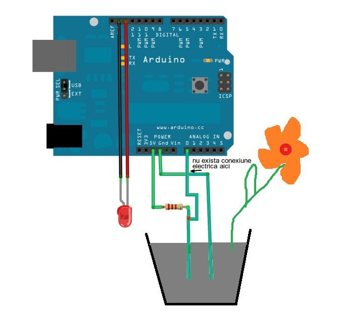
This is a simple Arduino project for a soil moisture sensor that will light up an LED at a certain moisture level. It uses the Arduino Duemilanove microcontroller. This project employs a soil moisture sensor to monitor the moisture content...

Ceramic gas sensors can be utilized to analyze the content of alcohol vapor. With the appropriate sensor circuit, it is possible to detect blood alcohol content. The operating principle is straightforward: if blood alcohol content is present in a...
.jpg)
The inductive sensor is a straightforward device at its core. It consists of a coil of wire with an electric current flowing through it. This sensor primarily ignores most objects that come close to the coil. However, when a...
In a class project, each student was required to select one of three technology platforms to design, simulate, prototype, and build, including PCB layout and ordering, all within a ten-week timeframe. The available platforms were: H-bridge Motor Controller, Infrared...
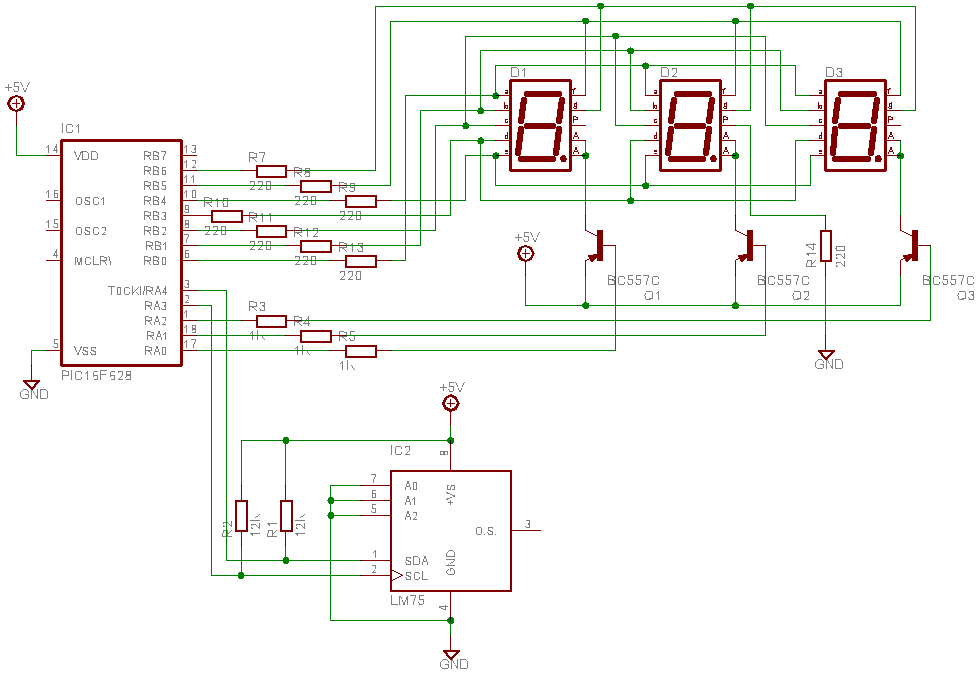
This is a test project assembled quickly on a solderless breadboard. It utilizes an LM75 temperature sensor to read the current temperature through the I2C communication protocol and displays the result. The project employs the LM75, a digital temperature sensor...