
GSM localizer without GPS Schematic
The localizer circuit design emphasizes simplicity and functionality, effectively combining a GSM/GPRS communication module with a microcontroller for real-time location tracking. The microcontroller's role as the central processing unit is critical, as it manages various input and output operations, ensuring seamless communication with the GSM module. The UART interface facilitates reliable data transmission and reception, allowing the system to process SMS messages and respond to requests efficiently.
The power management strategy is crucial for maintaining system stability, especially given the potential for voltage fluctuations during GSM transmissions. The inclusion of multiple filter capacitors along the power supply line serves to smooth out these fluctuations, protecting the microcontroller from potential disruptions. The choice of a 3.6-volt power supply, compatible with commonly available rechargeable battery types, enhances the circuit's portability and ease of use in various applications.
Moreover, the design incorporates a robust reset mechanism via the T1 transistor, ensuring that the GSM module can recover from any state of unresponsiveness without requiring physical intervention. This feature is particularly valuable in remote applications where accessibility may be limited.
Overall, the localizer circuit exemplifies an effective integration of communication technology with microcontroller capabilities, providing a reliable solution for location tracking and emergency signaling.The circuit our localizer is based on consists only of a quad-band GSM/GPRS module interfaced with a a microchip microcontroller which, after initializing the I/Os and UARTs it has at its disposal, puts the main program in a loop waiting for some event, which could be the arrival of an SMS or someone pressing the button P1 (that is, the logical 1/ 0 transition of the RB1 line, internally equipped with a pull-up resistor). In the event that an SMS is received, the localizer distinguishes between a message that is setting up a configuration and one that is requesting information regarding the position. Let us look more closely at the procedure that allows to find out the position, which is essentially the same in the case of manual requests as well as when pressing P1 (alarm or SOS): as soon as a request is received, the PIC orders the cellular module to connect to the Google Maps server in data mode (via GPRS, hence on the Internet) and to send a position request along with the cell ID to which Enfora is connected; now the localizer is ready to receive Internet-transmitted data on the RX channel of its own UART.
Once the localizer receives the data with conjectured position (latitude and longitude, approximate street or square location) and accuracy, it prepares an SMS and sends it to the number that requested it or to the one that is stored and associated with this particular alarm function. That is all: simple and functional. The cell phone is handled by the microcontroller by means of the RF1 line (through which it reads the RI, that is, the Ring Indicator used by the module to signal the arrival of a call), as well as RB4 line, which allows it to detect receipt of SMS messages.
RC7/RX1 and RC6/TX1 are, respectively, the reception and transmission lines of the UART, which is used not only to handle the cell phone`s functions (except for reset and power), but also to read and send SMS messages. The power function is handled by the RA4 line, which relies on PWRCTL to turn GSM1 on and off and which is essentially used to start the cell phone after initialization, that is, to turn it off and on again in the event it should get stuck and the reset function should not be enough to set it back to normal.
The reset function is handled by the PIC through the RC3 line, which relies on the T1 transistor, employed here as a static switch that effectively changes the module`s RST. This compound unit (that is, the cell phone and microcontroller) is powered through the SW1 switch by a continuous 3.
6-volt tension, applied to both + and PWR, which can easily be obtained from a 1. 2-V NiMh AAA rechargeable battery or from a 3. 7-V Li-Ion battery. Notice how many filter condensers are placed along the power line. They are needed to filter out disturbances produced by the input when the cell phone is transmitting disturbances that would otherwise create enough power fluctuations to block the microcontroller. 🔗 External reference
Related Circuits
L2 RFC (resistance 1MOhm with an inductor wrapped around it, composed of multiple coils made from fine insulated wire. The scratch of the inductor connects to the resistance, forming a parallel L-R circuit.) With capacitors C7 and C8, we...
This schematic has been developed as an exercise to learn about amplifiers. There are several aspects that require clarification and further understanding. The schematic in question likely involves a basic amplifier circuit, which may include components such as resistors, capacitors,...
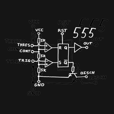
Classic 555 timer chip schematic circuit t-shirt by EEVblog picture on VisualizeUs - bookmark pictures and videos that inspire you. Social bookmarking of pictures and videos. Find your pictures and videos. The 555 timer IC is a versatile and widely...
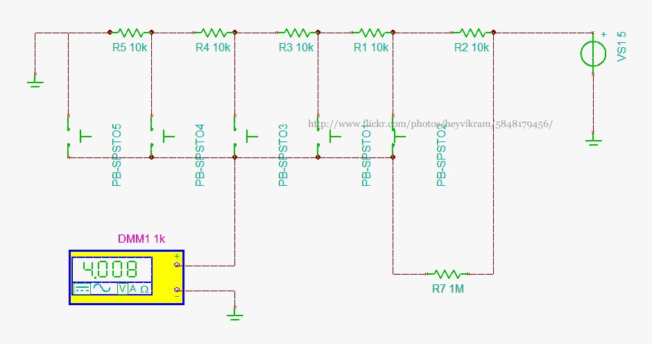
Connect a 5-way button/joystick to an Arduino using a single analog pin to quickly simulate it for verification of calculations before soldering. The voltages for the six states are 0, 1, 2, 3, 4, and 5. The 4V displayed...

The following circuit illustrates an Automatic Loudness Control Circuit Schematic. This circuit is based on the TL072 integrated circuit. Features include various functionalities. The Automatic Loudness Control Circuit is designed to adjust audio signal levels dynamically, enhancing the listening experience...
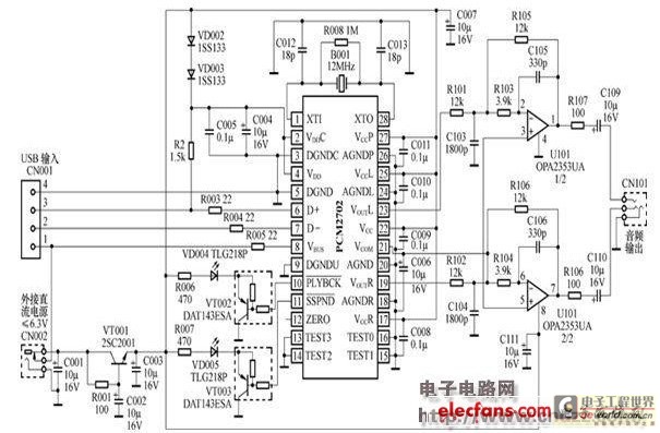
The peripheral circuit is straightforward, consisting of a DAC schematic circuit diagram for a USB interface that utilizes the PCM2702. The output of the circuit can be directly connected to a power amplifier and is capable of driving headphones...
Warning: include(partials/cookie-banner.php): Failed to open stream: Permission denied in /var/www/html/nextgr/view-circuit.php on line 713
Warning: include(): Failed opening 'partials/cookie-banner.php' for inclusion (include_path='.:/usr/share/php') in /var/www/html/nextgr/view-circuit.php on line 713