
Guitar Reverb Effect
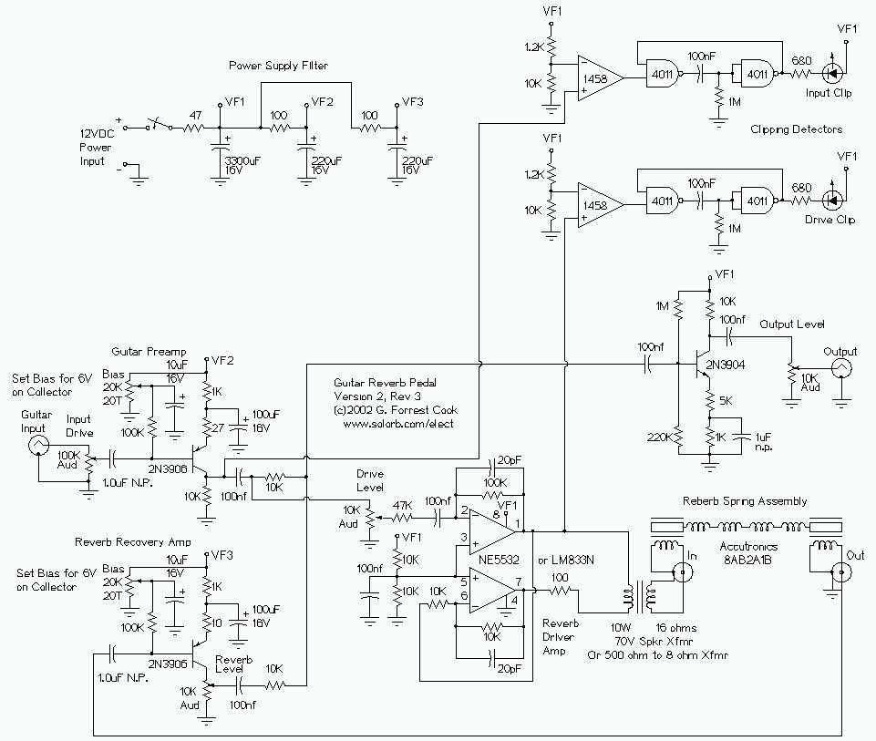
The reverb driver amp consists of a phase inverting push-pull circuit made from dual sections of a 5532 high quality audio op-amp. The transformer matches the impedance of the driver amplifier to the reverb driver coil and allows a dual phase driving signal to power a reverb coil with one grounded side. The transformer is a standard "70 volt" audio line transformer.
This circuit is designed for high-fidelity audio applications, particularly in guitar amplifiers, where clarity and dynamic range are crucial. The preamp stage employs a Class A amplifier configuration, which is known for its linearity and low distortion characteristics. The adjustable bias feature allows for fine-tuning of the amplifier's operating point, enabling optimal performance across various input signal levels. The inclusion of a 2N3906 PNP transistor minimizes noise, enhancing the overall signal integrity.
The output of the preamp is strategically routed to three distinct paths: the output mixer amplifier, the reverb driver amplifier, and the input clipping detector. This multi-path output design facilitates simultaneous processing of the audio signal, allowing for complex sound manipulation while maintaining clarity.
The reverb driver amplifier utilizes a phase-inverting push-pull configuration constructed from dual sections of a 5532 op-amp, which is recognized for its high-performance audio capabilities. This configuration not only improves efficiency but also enhances the dynamic response of the reverb effect, contributing to a richer sound experience.
The transformer plays a critical role in impedance matching between the driver amplifier and the reverb driver coil. By ensuring optimal impedance levels, the transformer enhances power transfer and minimizes signal loss. The use of a standard "70 volt" audio line transformer is particularly advantageous in this setup, as it allows for the delivery of a dual-phase driving signal to the reverb coil while maintaining one side grounded. This design choice simplifies the circuit layout and contributes to the reliability of the reverb effect in live performance settings.
Overall, this circuit exemplifies a sophisticated approach to audio signal processing, combining advanced components and configurations to achieve high-quality sound reproduction in guitar amplification systems.This circuit features clipping indicators on the preamp and reverb recovery stages, allowing for the optimal gain settings. The guitar input stage is a class A amplifier with adjustable bias. A 2N3906 PNP tranistor is used for a low noise design on this stage. The output of the preamp stage is sent to three places: the output mixer amp, the reverb driver amp, and the input clipping detector.
The reverb driver amp consists of a phase inverting push-pull circuit made from dual sections of a 5532 high quality audio op-amp. The transformer matches the impedance of the driver amplifer to the reverb driver coil and allows a dual phase driving signal to power a reverb coil with one grounded side. The transformer is a standard "70 volt" audio line transformer that is o 🔗 External reference
Related Circuits

The main component of the circuit has been achieved using an integrated circuit (IC) with a significant number of bulk components, primarily capacitors. The internal circuit is designed to output from the differential amplifier using a PNP unipolar configuration,...
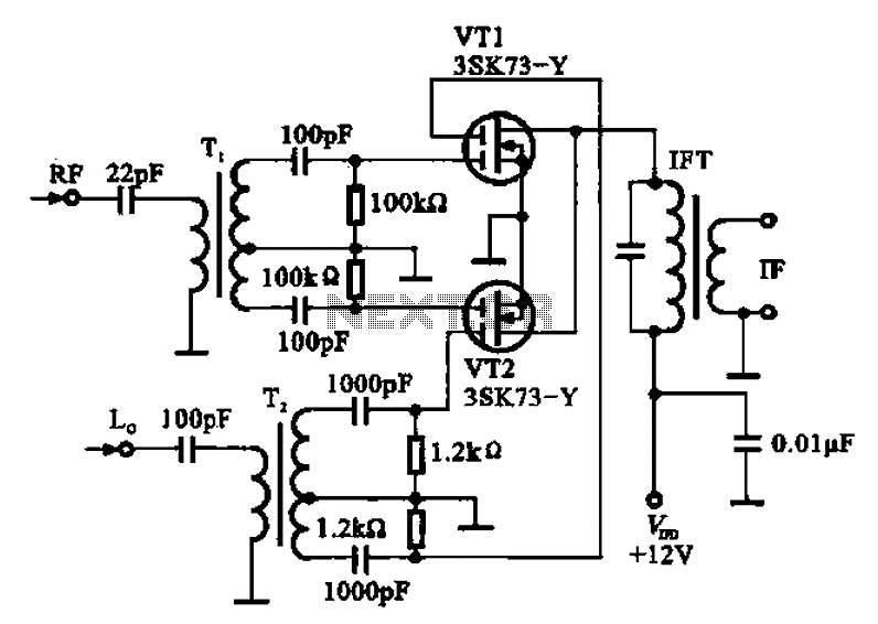
A balanced mixer circuit is illustrated using two dual-gate field effect transistors (FETs). The RF signal is coupled to the gates of these transistors through an input signal transformer (T1). Additionally, a local oscillation signal is introduced to the...
The integrated circuit (IC) generates various sound effects, with the output at Pin 3 amplified by a transistor. A 64-ohm loudspeaker can replace the 56-ohm resistor and 8-ohm loudspeaker. A two-pole, four-way switch controls the sound effects, with position...
This circuit uses the Holtek HT2884 IC to produce 8 different sound effects. All sound effects are generated internally by the HT2884 IC. Power is a 3 Volt battery, but the IC will work with any voltage between 2.5...
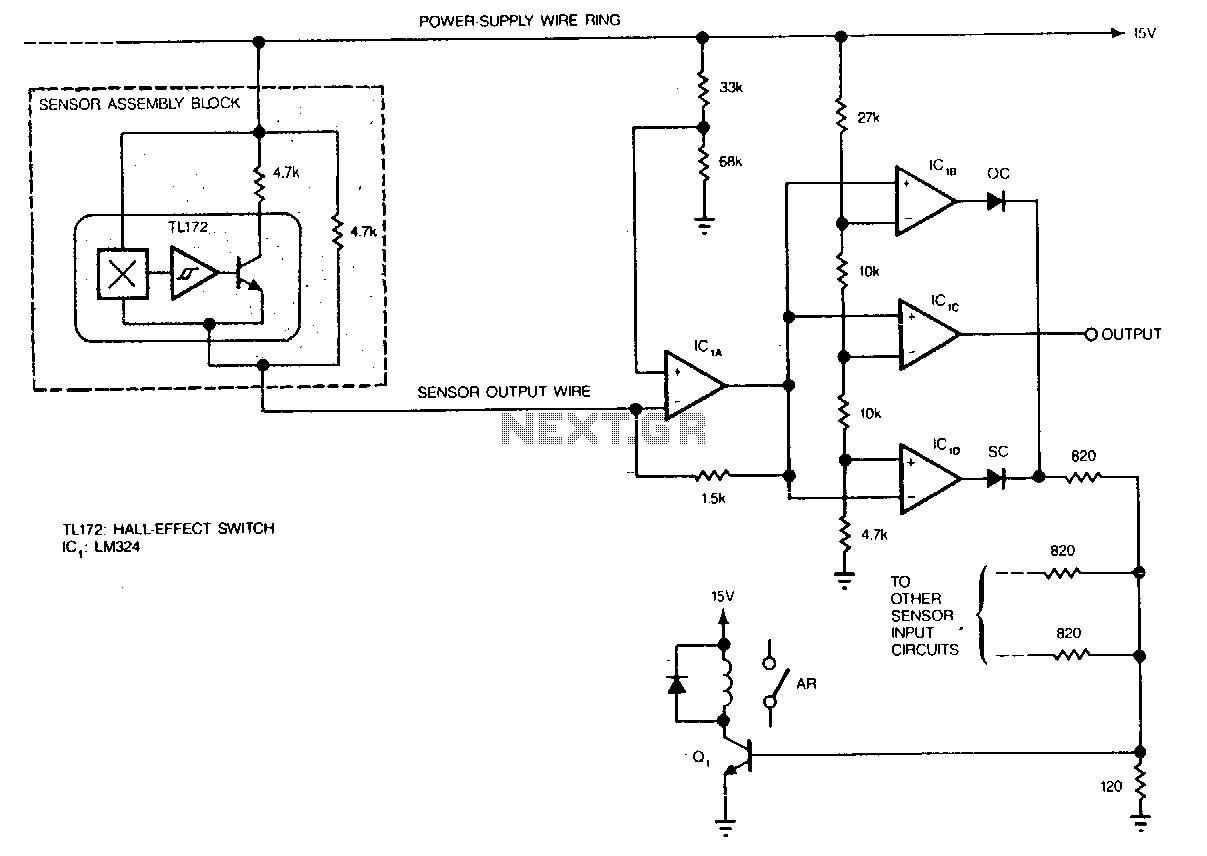
Hall-effect switches have several advantages over mechanical and optically coupled switches. They are insensitive to environmental light and dirt, do not bind, and do not experience mechanical wear. Their major disadvantage is the requirement of three wires per device....
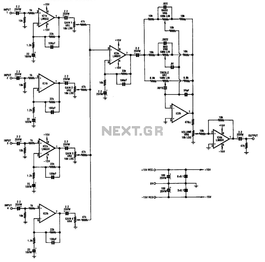
IC1-a, IC1-b, IC2-a, and IC2-b all operate with a gain of approximately 19. Their outputs are combined through level-control potentiometers, and the resulting signal is amplified by IC3-a before being sent to the tone-control stage IC3-b. Finally, the output...