
Gyraf Audio
The G9 preamplifier circuit utilizes a dual-channel configuration, allowing for simultaneous processing of two audio signals. Each channel includes a high-gain tube stage that enhances the audio signal while preserving its natural characteristics. The transformer-balanced output ensures that the signal is robust and less susceptible to interference, making it ideal for professional audio applications.
The design incorporates a high-pass filter that can be engaged to eliminate low-frequency noise, which is particularly useful in live sound situations or when recording vocals and instruments that may produce unwanted rumble. The phase reversal feature is crucial for resolving issues that can arise from microphone placement and phase cancellation, enabling users to achieve the best sound quality.
The user interface is designed for ease of use, with clearly labeled controls for gain adjustment and output levels. The rotary switch for selecting input types allows for quick changes between microphone and line inputs, accommodating various recording scenarios. The inclusion of phantom power is essential for powering condenser microphones, making the G9 versatile for different recording setups.
Safety features are paramount in the design, especially given the high voltages involved. The recommendation to use a resistor for discharging capacitors reflects best practices in audio equipment maintenance. Overall, the G9 project combines traditional tube technology with modern design principles to create a reliable and high-quality microphone preamplifier suitable for DIY enthusiasts and professional audio engineers alike.The G9 project is an adaptation of the Gyratec IX dual microphone/line/DI preamplifier to suit the DIY`ers demands. Searching the net, I`ve never come across a complete tube microphone preamp design, so I decided to share this version of our very popular design, the Gyratec IX.
It is a classic, conservative design, that easily matches the performa nce of even the most expensive and esoteric units I`ve been able to compare it to. I wish to thank Kev and Byron from Group DIY for test-piloting this project, and for their changes and comments on the original design. Without those guys this level of DIY-friendlyness would`nt have been even remotely possible. The G9 contains two channels of real-tube, high-gain, transformer-balanced microphone preamplifiers with additional line and instrument inputs and transformer balanced output.
It also features switchable phantom power, high-pass filter and phase reverse, as well as independent controls for input gain and output level - giving the user some creative options to work with. The signal path contains only tubes, transformers and passive components, to preserve your signal integrety.
VERY different from many "tubed" consumer products. But as we are not purists, we incorporate modern semiconductors in the powersupply sections - simply because this is way the easiest, cheapest and best solution available. For power amplifiers there`s quite an audible reason to use tubed power supplies, but for preamps I haven`t been able to spot any advantage so far.
I will try to update this page reguarly if anyone shows interest in its topics. Comments and corrections are extremely welcome, but I can`t promise to reply to all mail I receive. In "The Lab" - a forum on GroupDIY. org - there will surely be people that can and will answer most of your questions regarding the design, construction, and sourcing of parts. If you build this project and describe elements of the process, I`ll be more than happy to add it - or a link to it - here, so others can benefit from your experiences.
Notice that all information, schematics, layouts etc. are supplied "as is", and that we can in no way be held responsible for its acurateness, functionality or even safety. Gyraf Audio shall not be responsible and disclaims all liability for any loss, liability, damage (whether direct or consequential) or expense of any nature whatsoever, which may be suffered as a result of, or which may be attributable, directly or indirectly, to the use of or reliance upon any information, links or service provided through this website.
Now you know that. You have to take extreme caution when working with Mains and High Voltages. These voltages are lethal, and even the smallest error will be chatastrophic. And we like you to stay alive and well, so you can help other people sharing our bizarre interest for building retro-pro-audio-equipment. - NEVER work with live voltage switched on. Switch off, discharge, work, connect measuring equipment and power up. The G9 powersupply takes an average of 15 minutes to come down to non-dangerous voltages, providing that the tubes has had a chance to get hot.
But if there`s something really wrong, the lethal HT can stay for weeks! TAKE CARE! ALWAYS positively measure HT voltage on the PSU caps before touching ANYTHING. A good idea is to have a resistor, like 10K/2W, on a cable with two clips that you can attach to the caps for discharging. But please. Remember. Take care. As you can see from the schematic, the G9 is really a VERY simple, no-nonsense tube mic pre. Click on the schematic for a high-resolution version, suitable for printing The input is taken to Phantom resistors and the line input relay.
The line relay - as well as the Phantom power - is controlled by the front panel rotary switch, SW1: (line - mic - mic+p48). When in "line" mode, we set the input attenuation to -26dB, the Zin to~10KOhm - but still Z-matched to the transforme
🔗 External reference
Related Circuits
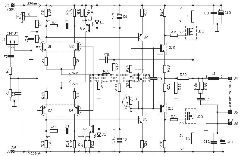
This HEXFET Audio Amplifier 65 Watts circuit diagram includes three circuit images. For a more comprehensive understanding, refer to the original post titled "HEXFET Audio Amp 65 Watts." The post not only provides circuit information but also includes a...
As shown in the figure, the 555 timer, resistors R1, RP1, and capacitor C1 form a controlled audio oscillator. The frequency of the oscillator is given by the formula f = 1.44 / ((R1 + 2 * RP1) *...
The purpose is supposedly to account for the fact that human hearing is less sensitive at low and high frequencies than in the upper midrange, and that this variation is dependent upon the sound intensity (SPL). The Fletcher-Munson curve...
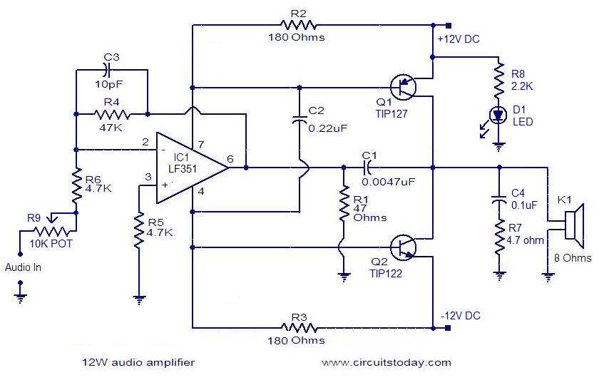
The circuit presented is a simple audio amplifier capable of delivering 12W to an 8 Ohm speaker. The operational amplifier IC TL081 serves as the preamplifier in this design. Alternatively, any operational amplifier with compatible power supply ratings can...

This active splitter for laptop audio output is powered by USB and provides an individual channel gain of 39 dB along with individual volume control for the headphone channel. The circuit utilizes two TDA2822M audio power amplifier integrated circuits...
A small audio test generator is highly effective for quickly tracing signals through audio equipment. Its primary function emphasizes speed over precision. Typically, a single sine-wave signal of approximately 1 kHz suffices, and distortion levels are not critically important....
Warning: include(partials/cookie-banner.php): Failed to open stream: Permission denied in /var/www/html/nextgr/view-circuit.php on line 713
Warning: include(): Failed opening 'partials/cookie-banner.php' for inclusion (include_path='.:/usr/share/php') in /var/www/html/nextgr/view-circuit.php on line 713