
H-bridge circuit
The circuit design described integrates several critical components to enhance performance and reliability in high-current applications. The use of Schottky diodes is particularly advantageous due to their fast switching capabilities and low forward voltage drop, which minimizes power loss during operation. The H-bridge configuration allows for bidirectional control of the motor, essential for applications requiring both forward and reverse motion. The choice of an optoisolator for signal isolation is prudent, as it protects sensitive control circuitry from high-voltage spikes generated during motor operation.
The incorporation of a Hex Inverter/Buffer circuit optimizes the control logic, ensuring that the relays operate correctly based on the desired motor direction. However, the design consideration regarding dynamic braking is noteworthy; while it simplifies the control logic, it may not be suitable for all applications, particularly those requiring smooth deceleration. The recommendation to adjust the gate resistor value reflects an understanding of the MOSFET's switching characteristics and the need for rapid gate drive signals to minimize transition losses and heat generation.
The proposal to utilize a dedicated MOSFET driver IC is an excellent enhancement, as it can provide the necessary gate drive current to achieve fast switching times, thereby improving overall efficiency. This is particularly important in PWM applications where the frequency can significantly impact performance. The discussion around resistor values and their impact on switching times indicates a thorough consideration of the circuit's behavior under various operating conditions.
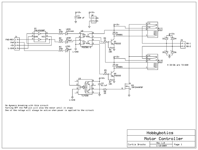
Overall, this circuit design demonstrates a thoughtful approach to high-current motor control, balancing cost, performance, and reliability while addressing potential issues related to component selection and circuit configuration.Develop a cheap high-current circuit and still use PWM. Specifically, did I get the flyback diodes right I placed the high-speed Schotkky clamping diodes in the circuit to protect the MOSFET from the CEMF generated by the motor as the power is switched on/off via the PWM signal. This will help keep the FET from generating to much heat and destroying itself. Also, the Optoisolator is a fast-switching type that will help ensure the MOSFET is switched on/off quickly. The opto has a fast rise/fall time. The relays are set up in an H-bridge configuration while the FET is used for the PWM signal. If anyone finds errors in this design please post them. Updated the schematic for those that want to save an I/O pin. There is a Hex Inverter/Buffer circuit (U1) that feeds the inputs of the Optoisolator (U2). If you look at the wiring for the Hex Inverter you will notice that the output of the second inverter feeds the input of the first inverter. So, when a logic 1 is placed across pin-3 it is inverted into a logic 0 which turns off the Reverse Relay.
A logic 0 is also placed at the input of the first inverter which gets converted to a logic 1 on its output and turns on the Forward Relay. By using the inverter circuit you will no longer have the capability for dynamic breaking. In other words, one of the relays will be active as longs as powered is applied to the circuit. Disabling the PWM signal will keep the motor from turning. I have used something very similar with RC cars that don`t need to go in reverse much. only I use a single DPDT relay for direction with it being energized for reverse. The only thing that I can see, and this depends on the intended design, is that you have a HARD electrical brake to the motor when the FWD and REV relays are in the same position.
This can cause abrupt stops if your intention is to free-wheel. But as I said it depends on the design, in some cases this feature might be desirable. Thanks for the reply. The intentions are to ramp the motor down to a stop and then change the direction as to not have an abrupt stop. Thanks for the suggestions. I put this circuit together as I didnot have any DPDT relays for a simpler circuit. With this circuit my intentions are to be able to adjust the current requirements based on the current limits of the relay and FET.
This circuit will operate at about 20 to 40 Amps. The Shotkky diodes and FET will have a heatsink on them. There will also be an inline fuse for further protection. One concern is the 10 kOhm resistor from gate to source of the power mosFET. I`d recommend ~1 kOhm. The fast switching times of less than 10 microseconds for the PS2501 optocoupler are specified for resistance of 100 to 2000 ohms, and the switching time with a 10kohm resistor is more like 100 microseconds. Also the RC time constant of the 10 kOhms with the 1400pF of the transistor would slow down the discharge side of the transition.
It depends too on the form/frequency of the PWM. I was thinking of using a Microchip TC4427 1. 5A Dual High-Speed Power MOSFET Driver or TLP250 Photocoupler Power MOSFET Gate Driver instead of driving the MOSFET with the PS2501 optocoupler as it was suggested that it will provide more current to the gate of the FET. Any thoughts on whether this will be better than the current design The driver chip is a good idea for fast transitions both up and down.
Be sure to ground the unused inB. With this chip and its totem pole output, there is no need for a low 1k resistor for the pulldown R9, so 10k or 100k would be fine. The LED on the input of the driver chip is going to keep it pulled low anyway. Tracy, what if for some reason, the power to the driver fails, or the driver fails and the gate is left floating Isn`t that what the pulldown on the gate-source is for To ensure the mosfet remains off I`m just a litt
🔗 External reference
Related Circuits
This schematic illustrates a highly sensitive microphone preamplifier circuit designed to amplify the gain of a microphone or enhance audio signals originating from a microphone. The circuit is straightforward, comprising only a few components, and can be assembled in...
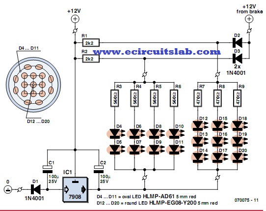
LEDs are increasingly utilized in motor vehicles, replacing traditional incandescent lamps due to their superior energy efficiency and extended lifespan. This article outlines a straightforward LED tail light specifically designed for motorcycles, scooters, and mopeds. There is a notable...
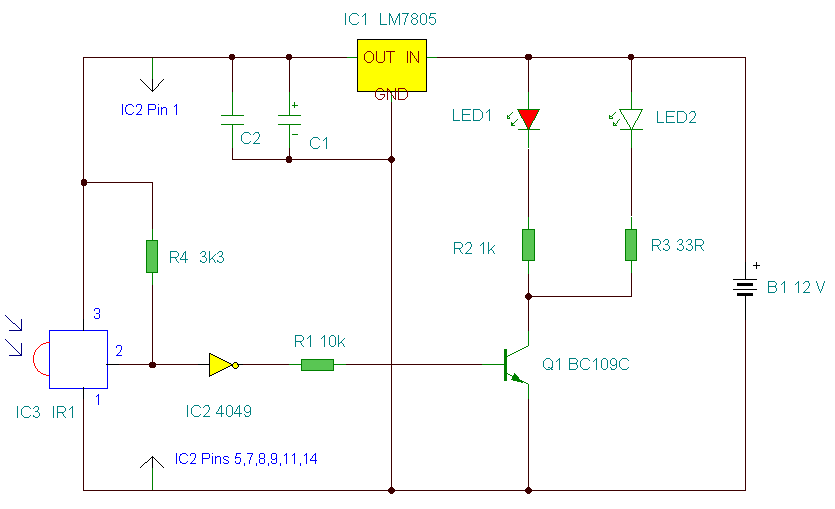
This is an improved IR remote control extender circuit. It has high noise immunity, is resistant to ambient and reflected light and has an increased range from remote control to the extender circuit of about 7 meters. It should...
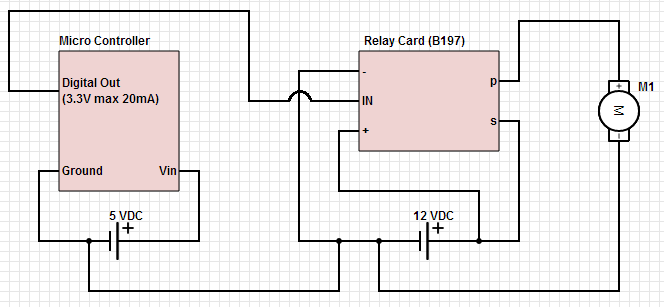
The objective is to control a 12 VDC device (on/off) from a microcontroller using a relay card. The relay requires a 12 VDC operating power supply. To achieve the control of a 12 VDC device using a microcontroller and a...
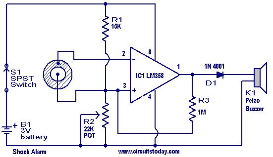
This is a simple shock-sensitive alarm circuit with numerous applications, ranging from home use to automobiles. The primary application of this circuit is as an anti-theft alarm for vehicles. A piezoelectric sensor is employed as the shock sensor and...

This circuit describes the sensing of air flow using the PIC16C781 microcontroller. It utilizes Programmable Switch Mode Controllers (PSMC) that combine an Integrated Operational Amplifier, a Digital-to-Analog Converter (DAC), and a gated timer to create a thermally operated air...
Warning: include(partials/cookie-banner.php): Failed to open stream: Permission denied in /var/www/html/nextgr/view-circuit.php on line 713
Warning: include(): Failed opening 'partials/cookie-banner.php' for inclusion (include_path='.:/usr/share/php') in /var/www/html/nextgr/view-circuit.php on line 713