
h bridge Where to place decoupling capacitor
In the context of driving a motor, proper decoupling is critical to ensure stable operation and to protect both the motor and the control circuitry from voltage transients. Voltage spikes can occur when the motor is switched on or off, or when it experiences sudden changes in load. A decoupling capacitor acts as a local energy reservoir, providing instantaneous current to the IC during these transient events, thus smoothing out the voltage variations.
The optimal placement of the decoupling capacitor is crucial. It is generally advisable to place the capacitor as close to the power supply pins of the IC as possible. This minimizes the inductance of the traces connecting the capacitor to the IC, allowing it to respond more effectively to rapid changes in current demand. If the capacitor is located too far from the IC, its ability to filter out high-frequency noise may be compromised.
While some may suggest placing the decoupling capacitor between the battery terminals, this approach may not provide the same level of immediate response to voltage spikes affecting the IC. The capacitor should ideally be placed directly across the power supply pins of the IC to ensure that it can effectively decouple the power supply from the IC's operational demands.
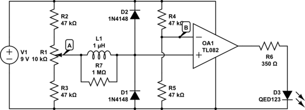
In summary, for this motor-driving circuit, the decoupling capacitor should be positioned as close as possible to the IC's power supply pins to achieve optimal performance and protection against voltage spikes. Proper layout and placement are essential to ensure the reliability and efficiency of the circuit.Using this(also below in question) circuit to drive a motor, and I heard I should put a decoupling cap in there to smooth out voltage spikes. I have been told to put it close to the ic, and I have also been told not to put it in front of the ic, but between the battery terminals.
Where should it go Here`s an image of how I have it worked out on the breadboard: @MikeJ-UK my first thought when I saw the truth table was "Who would ever design a chip that forces you to always have 2 pins inverted of each other or a motor breaks. " Then I realized what it was trying to mean. Kellenjb Apr 8 `11 at 14:26 🔗 External reference
Related Circuits
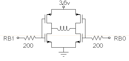
Drive a small (3.6V, <1A) brushed motor bidirectionally with a PIC microcontroller (MCU). The available space is extremely limited, so a single 3.6V power supply will be used for both the motor and the PIC, with minimal drive circuitry required. There is no dedicated motor driver IC that operates at this low voltage, making a discrete H-bridge the most suitable drive arrangement. The NXP PMV30UN and PMV32UP have been identified as suitable N-type and P-type drive MOSFETs. Since both the PIC and the motor share the same power supply, it is questioned whether it is possible to eliminate the usual driving circuitry for an H-bridge and connect the transistors directly to the MCU pins. Potential pitfalls of this approach should also be considered. To design a bidirectional motor drive circuit using a PIC microcontroller and a discrete H-bridge configuration, the following considerations must be taken into account. The H-bridge consists of four MOSFETs arranged in a configuration that allows current to flow through the motor in either direction, enabling bidirectional control. The NXP PMV30UN and PMV32UP MOSFETs are suitable candidates due to their low on-resistance and capability to operate at the required 3.6V supply voltage. The connections between the PIC MCU and the MOSFETs should be made with consideration of the gate drive requirements. Directly connecting the MOSFET gates to the MCU pins can be feasible, but it is essential to ensure that the MCU can provide sufficient gate drive voltage to fully turn on the MOSFETs. A typical threshold voltage for these MOSFETs is around 1V, so the output high level from the PIC should exceed this threshold to ensure efficient operation. It is also critical to incorporate pull-down resistors on the gate pins to prevent the MOSFETs from floating when the MCU is in a high-impedance state. This will help avoid unintended motor activation. Additionally, using gate resistors can help dampen any oscillations and limit inrush current during switching, which could potentially damage the MOSFETs or the MCU. Another consideration is the back EMF generated by the motor when it is switched off or when changing direction. This can induce voltage spikes that may damage the MCU or the MOSFETs. To mitigate this risk, flyback diodes should be placed in parallel with each MOSFET to provide a path for the back EMF, ensuring safe operation of the circuit. Thermal management is also a critical aspect of the design. Although the MOSFETs are rated for low on-resistance, continuous operation near their current limits can lead to significant heat generation. Adequate heat dissipation measures, such as heat sinks or thermal pads, should be considered. In summary, while it is possible to connect the MOSFETs directly to the MCU pins, careful attention must be given to gate drive requirements, protection against back EMF, and thermal management to ensure reliable and efficient operation of the bidirectional motor drive circuit.
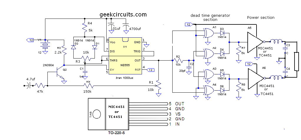
This document presents an improvised circuit model designed to eliminate unwanted DC offset voltage from the output, which affects previously discussed circuits. All prior circuits were intended as low-power Class D amplifier sources suitable for driving headphones through a...
This is an affordable buffer circuit designed for mixing passive pickups with EMG active pickups, or for buffering piezo pickups to be combined with magnetic pickups. The frequency response of the circuit is nearly flat, and the noise level...
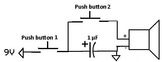
This project demonstrates how a capacitor can supply a pulse signal to a speaker. A capacitor is charged and then discharges its voltage to a speaker, which acts as a transducer that converts electrical signals into sound. The result...
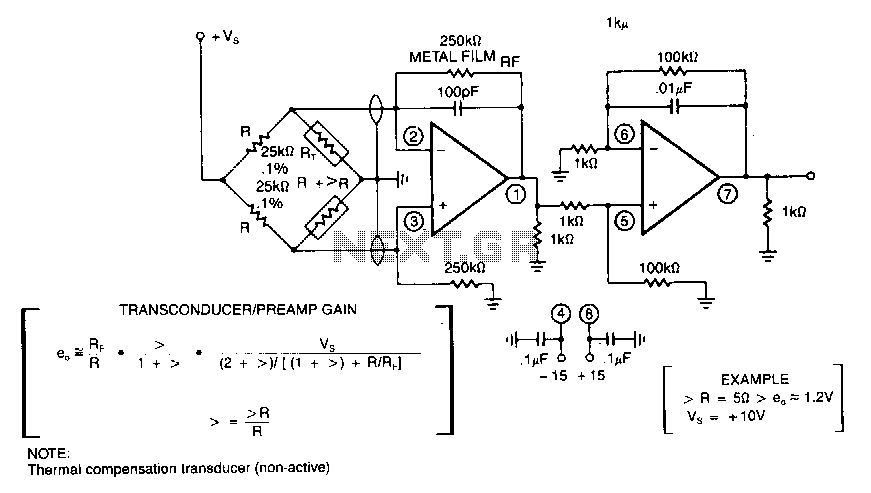
In applications involving strain gauges, accelerometers, and thermal sensors, a bridge transducer is often utilized. Typically, the sensor elements are high-resistance units that necessitate an equally high bridge resistance for optimal sensitivity. Consequently, this type of circuit requires an...
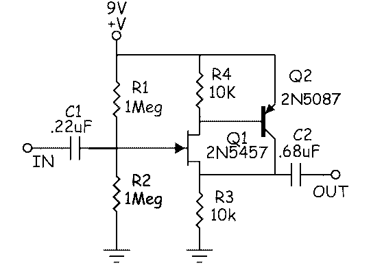
The circuit above is a canonical AC coupled common emitter amplifier, which is typically used as a linear amplifier rather than a switch that activates when the input exceeds a certain level. The AC coupled common emitter amplifier is...