
Hall-Sensor Current Monitor
The Hall-effect sensor circuit is designed to provide accurate measurements of DC current by utilizing the principles of magnetism and semiconductor technology. The Hall-effect sensor detects the magnetic field generated by the current flowing through the wire wrapped in the toroid. The output voltage (Vh) produced is directly proportional to the strength of the magnetic field, and consequently, the current flowing through the wire.
In practical applications, such as monitoring an automobile alternator, the circuit is configured by connecting the vehicle's battery to the VB terminal and ground. The wire is wrapped through the toroid, and the circuit is calibrated to ensure accurate readings. The design allows for flexibility in measurement, as multiple turns of wire can be wrapped through the toroid to scale the current measurement appropriately. For example, wrapping ten turns would allow for measuring up to 1 A full-scale, enhancing sensitivity for lower current measurements.
The circuit's output characteristics are crucial for integration into broader systems. When the input current (I) is zero, both VH and Vout are zero, establishing a baseline for the sensor's operation. The output can be adjusted for gain and offset, allowing the user to set the output voltage to reflect the desired scaling of current measurement, specifically 1 V per 10 A in this case.
The components selected for this circuit are critical for its performance. The tantalum capacitors (C1 and C2) from Sprague provide stable capacitance and reliability, while the inductor (L1) from Caddell-Burns ensures proper inductive behavior in the circuit. The thin-film resistor network (R1A, R1B, and R1C) provides precision resistance values, essential for accurate scaling and calibration. Finally, the Hall-effect sensor (CS1) from Microswitch is a key component that directly influences the accuracy and responsiveness of the current measurement.
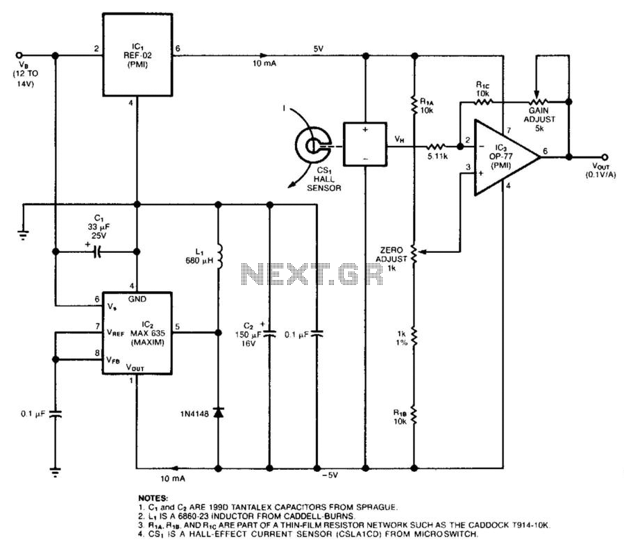
Overall, this Hall-effect sensor circuit is well-suited for applications requiring precise DC current measurement, offering scalability and adaptability depending on the specific requirements of the system it is integrated into. The circuit uses a Hall-effect sensor, which consists of an IC that resides in a small gap in a flux-collector toroid, to measure dc current from 1 to 40 A. Wrap the current-carrying wire through the toroid; the Hall voltage Vh is then linearly proportional to the current (/). The current drain from Vb is less than 30 mA. To monitor an automobile alternator"s output current, for example, connect the car"s battery between the circuit"s VB terminal and ground, and wrap one turn of wire through the toroid (or, you could wrap 10 turns—if they"d fit—to measure 1 A full-scale).
When 7=0 V, the current sensor"s (CSl"s) VH output equals one-half of its 10-V bias voltage, VH and Vout arc zero when I is zero; you can then adjust the output gain and offset to scale Vout at 1 V per 10 A. 1. C1 and C2 ARE 199D TANTALEX CAPACITORS FROM SPRAGUE. 2. L1 IS A 6860-23 INDUCTOR FROM CADDELL-BURNS. 3. R1A, R1B AND R1C ARE PART OF A THIN-FILM RESISTOR NETWORK SUCH AS THE CADDOCK T914-10K 4. CS1 IS A HALL-EFFECT CURRENT SENSOR (CSLA1CD) FROM MICROSWITCH. 🔗 External reference
Related Circuits
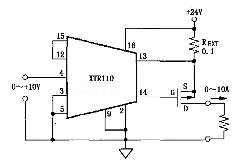
When the output current exceeds 40mA, the XTR110 requires the use of an external resistor (REXT) instead of the internal 50-ohm resistor (R9). REXT should be connected between pin 13 and pin 1. The value of REXT is determined...
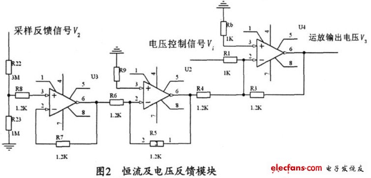
The output current range of the parameter current regulator is limited, and its precision is not high. Connecting the feedback adjustment type output current of the current-stabilized power source in series results in lower efficiency. The steady current source...
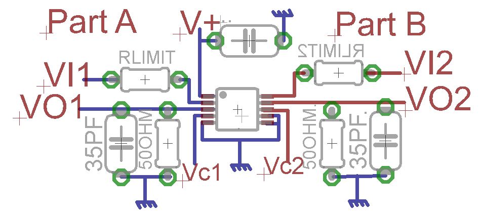
A request for advice regarding the connection diagram of the MAX4685 analog switch is presented. The circuit involves two inputs, VI1 and VI2. The MAX4685 is a low-voltage, dual analog switch designed for low on-resistance and high-speed switching applications. In...
Assuming a 5V output can be achieved after adjusting the potentiometer, will the 240-ohm resistor limit the current, or is there a need to add additional components? If it does limit the current, it is expected that the power...
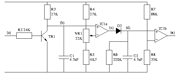
IC1 is a dual operational amplifier. In this circuit, each op-amp functions as a voltage comparator. When the voltage at the positive input exceeds the voltage at the negative input, the output transitions to a high state. Conversely, when...
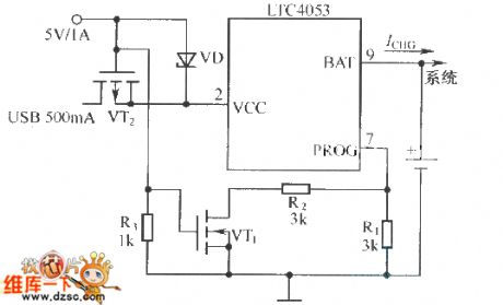
The constant current charging circuit, which consists of a three-port voltage stabilizer, is illustrated in figure 2-21. The electric potential difference between pin-1 and pin-2 of the LM317 is 1.25V. Ignoring the shunting effects of resistors R3, R1, and...
Warning: include(partials/cookie-banner.php): Failed to open stream: Permission denied in /var/www/html/nextgr/view-circuit.php on line 713
Warning: include(): Failed opening 'partials/cookie-banner.php' for inclusion (include_path='.:/usr/share/php') in /var/www/html/nextgr/view-circuit.php on line 713