
Handy Pen Torch Circuit
The circuit design for the handy pen torch is characterized by its simplicity and efficiency, making it an ideal project for electronics enthusiasts. The use of two LM334 precision adjustable shunt regulators allows for accurate current control, ensuring that the power white LEDs emit a consistent brightness without risk of damage due to overcurrent. The choice of a 4.8V Ni-Cd battery pack ensures that the system remains portable and rechargeable, catering to the need for a compact light source.
The inclusion of a constant current charger circuit demonstrates a thoughtful approach to battery management. The BC636 transistor efficiently regulates the charging process, maintaining an optimal current level to prolong battery life. The use of a step-down transformer, along with rectifier diodes and a filter capacitor, forms a reliable power supply for the charger, ensuring stable performance.
The design also emphasizes safety with the implementation of a diode to prevent reverse current flow during charging, protecting the battery from potential damage. The overall construction of the circuit on a general-purpose PCB facilitates ease of assembly and troubleshooting.
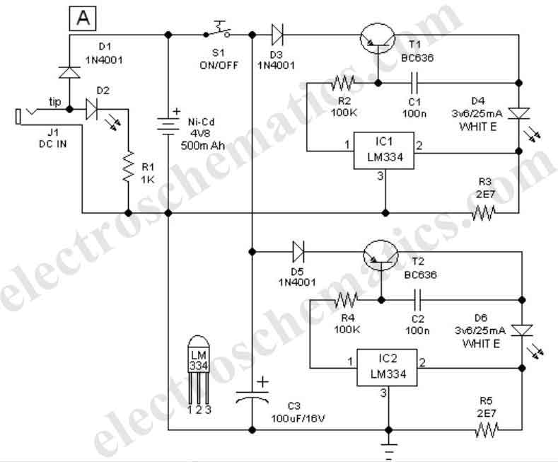
In summary, this handy pen torch circuit is a practical and effective solution for portable lighting needs, combining low component count with robust performance features. The final product, once housed in a protective enclosure, is not only functional but also visually appealing, making it suitable for various applications.This easy to construct Handy pen torch electronic circuit and low component count, uses two power white LEDs for lighting. Low volt (4. 8V dc) supply available from the built in rechargeable Ni-Cd battery pack is first converted into two channel (independent) constant current sources by two pieces of the renowned precision adjustable shunt regul
ator chip LM334 (IC1 and IC2). Around 25 mA at 3. 6 volt dc is available at the output of these ICs. This regulated dc supply is used to drive two power white LEDs D4 and D6. Resistors R3 and R5 limlits the output current (and hence the light output) of IC1 and IC2 circuits respectively. Diode D1 works as an input polarity guard cum reverse current flow preventer. Capacitor C1 is a simple buffer for circuit stabilization. After succesful construction, preferably on a small piece of general purpose PCB, enclose the whole circuit in a suitable and attractive pen torch cabinet.
If necessary, drill suitable holes in the cabinet to attatch the dc socket, on/off switch and the input indicator etc. In prototype, commonly available 4. 8 volt/500mah Ni-Cd battery pack (for cordless telephones) is used. One very simple but reliable ac mains powered battery charger circuit for the handy pen torch is also included here.
Basically the pen torch circuit is a constant current charger wired around Transistor T1 (BC636), powered by a 12v/350mA step down transformer and associated componentsD1, D2 and C1. Unregulated 12 volt dc available from the input power convereter circuit, comprising step down transformer(TRF), rectifier diodes (D1, D2) and filter capacitor (C1), is fed to T1 through a current limiting resistor R1.
Grounded base PNP transistor T1 here works as a constant current generator. With 22 ohm resistor for R1, the charging current available at the output of the charger is near 50 mA. Red LED (D3) provides a fixed voltage reference to the base of T1, with the help of resistor R2. (During charging process, Diode D1 in the main circuit prevent reverse current flow from the battery pack when charging input supply is absent.
) After construction of the pen torch circuit, fit the assembled unit inside a small plastic enclosure for safety and convenience. Pen Torch Electronic Circuit Schematic If necessary, drill suitable holes in the cabinet to attatch the dc socket, on/off available 4.
8 volt/500mah Ni-Cd battery pack (for cordless telephones) is Name: Tridev Kripa Total articles written: 54. Visit the author website 🔗 External reference
Related Circuits

The interface circuit is placed between the computer's standard video signal output terminal and the television. It amplifies the standard 1V (Peak-to-Peak) video signal to 3V (Peak-to-Peak). The negative feedback circuit consists of transistors T1 and T2, providing a...
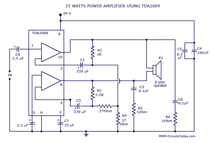
Power amplifier circuit diagram with schematics. This simple audio power amplifier circuit is designed for 25 watts output power using TDA 2009 IC, which has two channels (stereo), 12.5 W for each channel. The described power amplifier circuit utilizes the...
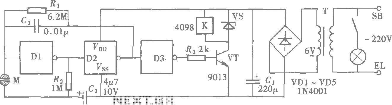
A CMOS gate exhibits high input impedance, which allows it to respond to changes in input levels due to human contact, thereby triggering the toggling of gates. The circuit utilizes this characteristic to create a touch lamp switch. The...
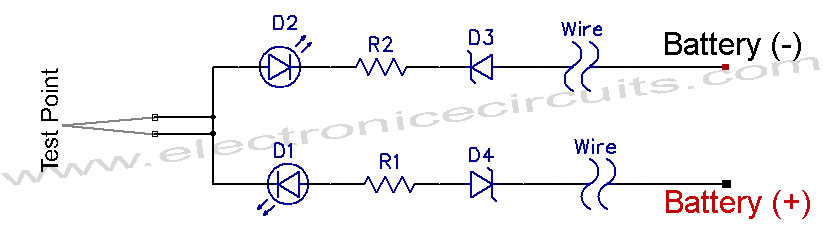
12V Vehicle Electrical Wiring Tester Circuit. This tester is useful for checking vehicle electrical circuits. Two LEDs indicate whether the circuit is live or not. The 12V vehicle electrical wiring tester circuit is designed to provide a simple yet effective...
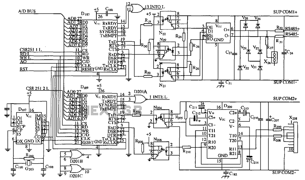
As shown in the figure, D187 is a universal asynchronous receiver-transmitter (UART). Its RX/TX signals are received through optocouplers N21, N22, and N29, facilitating RS-485 communication. The interface receiver/transmitter D28 and microprocessor D211 are completely optically isolated. D197 serves...
These two tank circuits appear to broaden the operating spectrum. The accompanying information sheet indicates that when both circuit stages oscillate at the same frequency, the power output reaches its maximum. This suggests that if the tunable tank circuit...
Warning: include(partials/cookie-banner.php): Failed to open stream: Permission denied in /var/www/html/nextgr/view-circuit.php on line 713
Warning: include(): Failed opening 'partials/cookie-banner.php' for inclusion (include_path='.:/usr/share/php') in /var/www/html/nextgr/view-circuit.php on line 713