
Hardware Schematics
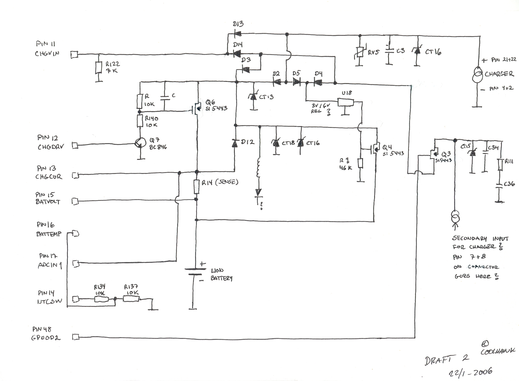
The described circuit schematic outlines a dual power input system designed to facilitate charging from either a USB port or a conventional external charger. The circuit is structured to ensure compatibility with both power sources, providing flexibility in charging methods.
The primary components of the schematic include a Schottky diode, which is crucial for preventing reverse current flow that could damage the circuit. The use of a Schottky diode is particularly advantageous due to its low forward voltage drop, which enhances charging efficiency. The circuit also features a transistor labeled as Q7, which likely acts as a switch or regulator to manage the power supply to the device.
In the event of incorrect charger connections, such as the one experienced with the Samsung charger, the circuit design must incorporate protective measures to safeguard against over-voltage or incorrect polarity. The schematic should include appropriate fuses or resettable polyfuses to prevent component damage during such occurrences.
The pinout referenced should provide clear identification of each connection point, facilitating accurate assembly and troubleshooting during the circuit's implementation. This information is critical for users to ensure proper connections and to avoid similar incidents in the future.
Overall, this schematic serves as a foundational design for a versatile charging circuit, emphasizing the importance of component selection and protective measures to enhance durability and functionality in various charging scenarios.This is a very crude handdrawn schematic version 2. I`ll pop it into Protel later when I get the time. But it does give you a very handy overview of the circuit where it`s possible to charge from 2 different sources. Either by USB or normal charger. Also refer to the pinout located here on the wiki site. I made this since I got a X5 in where the o wner had connected a Samsung charger, and of course boooom pooff smoke. The schotkky diode and Q7 was burned out, after they were replaced the X5 is now charging again. 🔗 External reference
Related Circuits
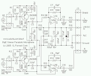
The mini condenser microphone converts sounds into an electrical signal. Resistor R1 provides bias for the condenser microphone's internal amplifier transistor. The 2N3906 PNP transistor acts as a low-noise microphone input amplifier. The 10K gain potentiometer is used for...
The figures below illustrate using opamps as active 2nd order filters. Three 2nd order filters are shown, low pass, high pass, and bandpass. Each of these filters will attenuate frequencies outside their passband at a rate of 12dB per...
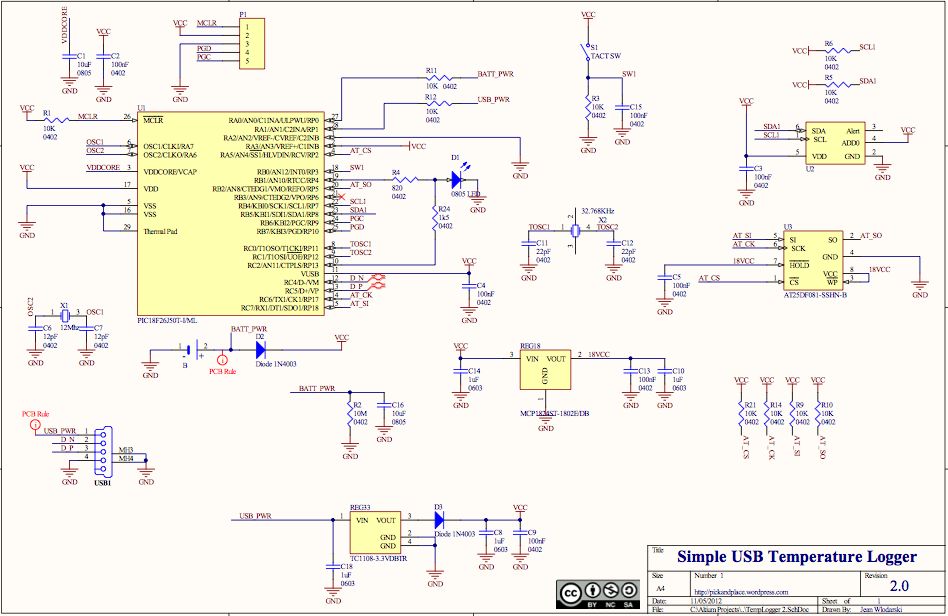
The source code features a FAT12 filesystem that can be utilized to create custom flash drives for various projects. This source code is based on the Microchip Applications libraries for the Device Mass Storage SD Card data logger using...
The circuit consists of two main components: (1) a power supply circuit featuring a transformer (T) that steps down AC 220V to 33V, followed by a full-wave rectifier, a filter, and a three-terminal regulator that outputs +24V. This circuit...
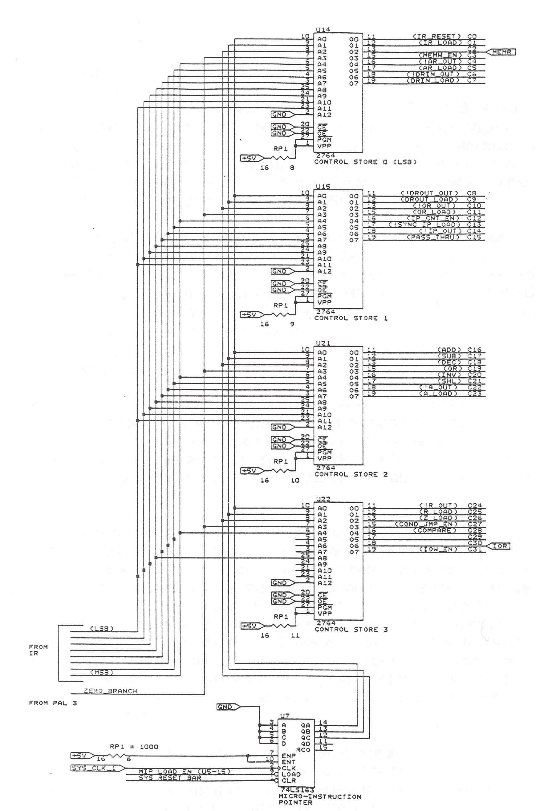
The datapath consists of registers, an ALU, and an internal system bus. Registers are fast memory locations internal to the CPU, distinct from main system memory, and serve as temporary storage during calculations. The ALU is a combinational logic...
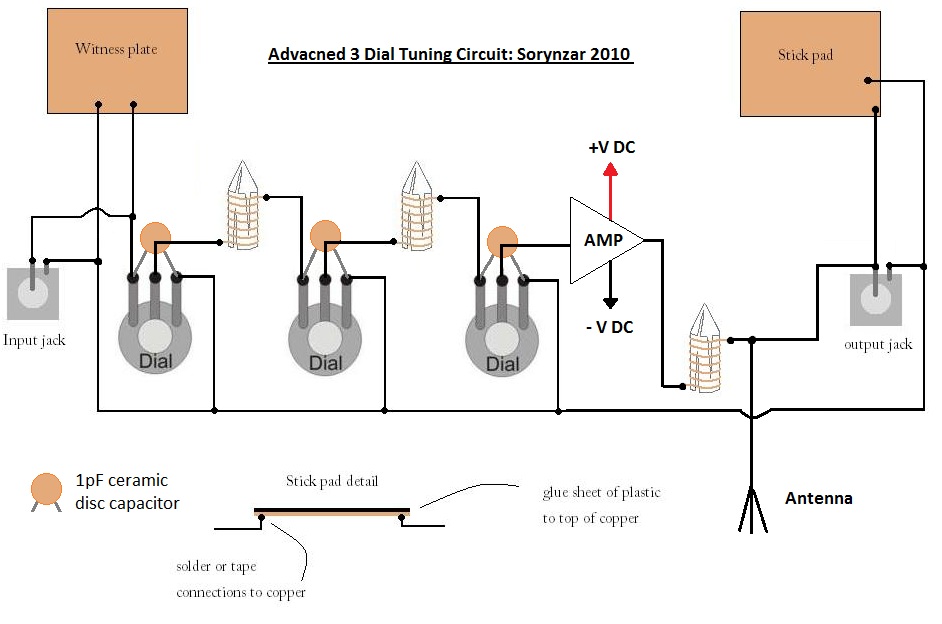
An advanced radionics schematic designed to enhance the power output of a tuning circuit. This schematic outlines a sophisticated approach to improving the efficiency and output power of a tuning circuit used in radionics applications. The circuit typically includes a...
Warning: include(partials/cookie-banner.php): Failed to open stream: Permission denied in /var/www/html/nextgr/view-circuit.php on line 713
Warning: include(): Failed opening 'partials/cookie-banner.php' for inclusion (include_path='.:/usr/share/php') in /var/www/html/nextgr/view-circuit.php on line 713