
Having a current negative feedback speed control system
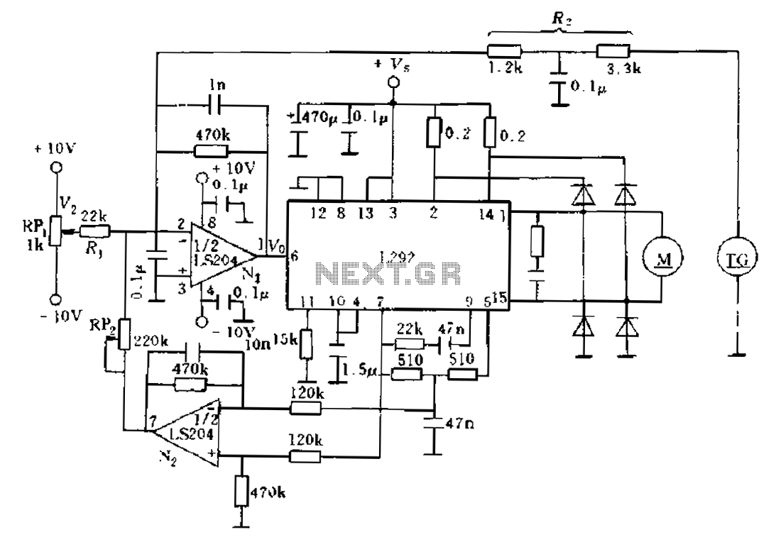
In this circuit design, the L292 operational amplifier serves as the core component for current feedback applications. The configuration emphasizes the importance of the feedback loop in maintaining the stability and accuracy of the output signal. The feedback signal is processed through an error amplifier summing junction, where the incoming signals are compared against a reference voltage to determine the necessary corrections.
The choice of a 510-ohm resistor in the sampling path is critical, as it influences the gain and bandwidth of the operational amplifier. This resistor helps in setting the desired impedance level, ensuring that the operational amplifier operates within its optimal range. The two-foot distance from the sampling point to the error amplifier is designed to minimize any potential signal degradation due to transmission losses, thereby preserving the integrity of the feedback signal.
The use of a potentiometer (RP) for adjusting the feedback coefficient allows for fine-tuning of the circuit's response to varying load conditions. By appropriately adjusting RP, the designer can suppress unwanted variations in speed that may arise from fluctuations in load current. This capability is essential in applications where consistent performance is required, particularly in systems with dynamic load characteristics.
Overall, this circuit exemplifies a well-thought-out design approach, integrating feedback mechanisms and component selection to achieve reliable operation in current feedback applications. The careful consideration of distances, resistances, and tuning elements ensures that the system remains responsive and stable under varying operational conditions.Another solution would be to improve the current feedback signal to an error amplifier summing junction incorporated into, a current feedback loop to increase. Figure this scen ario. L292 circuit, and electrical current is proportional to the average current in the external circuit of motivation 5 feet and 7 feet between the flows As shown above, sampling through an operational amplifier adjustment from 510fl resistance after delivery to the error amplifier 2 feet. Feedback coefficient by the potentiometer RP, tuning. Appropriately adjusted RP, suppressed the influence of load current on speed.
Related Circuits
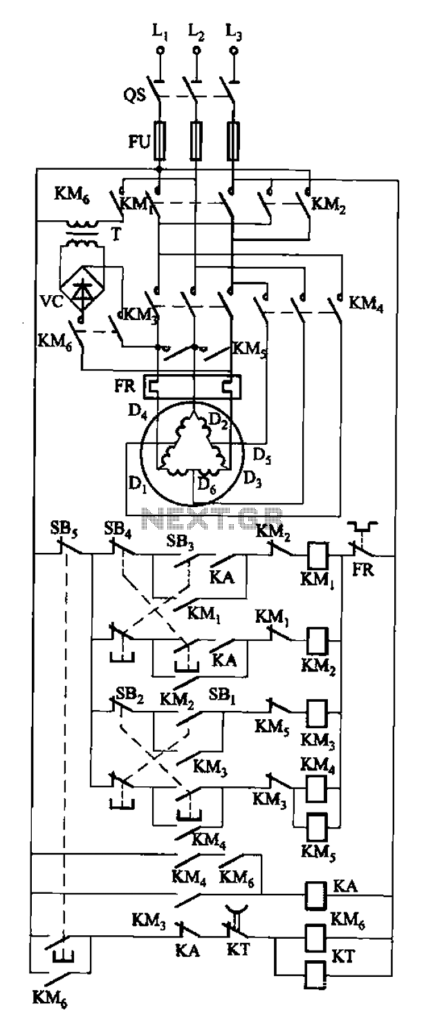
The circuit depicted in Figure 3-108 includes various control buttons: SB3 for the forward button, SI for the reverse button, SBi as the low start button, SB2 for the speed start button, and SBs for the stop button. KMs...
A discussion took place on synth-diy regarding the challenges of constructing a voltage-controlled oscillator with a sawtooth wave output, where the duty cycle (the ratio of ramp-up time to ramp-down time) can be adjusted using a separate control voltage....
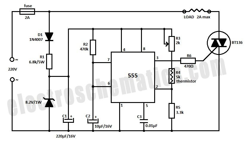
Construct a temperature controller circuit using the 555 integrated circuit (IC) in combination with a thermistor resistor divider. The benefit of this design is that it does not require a well-regulated power supply. The resistor divider network comprises an...
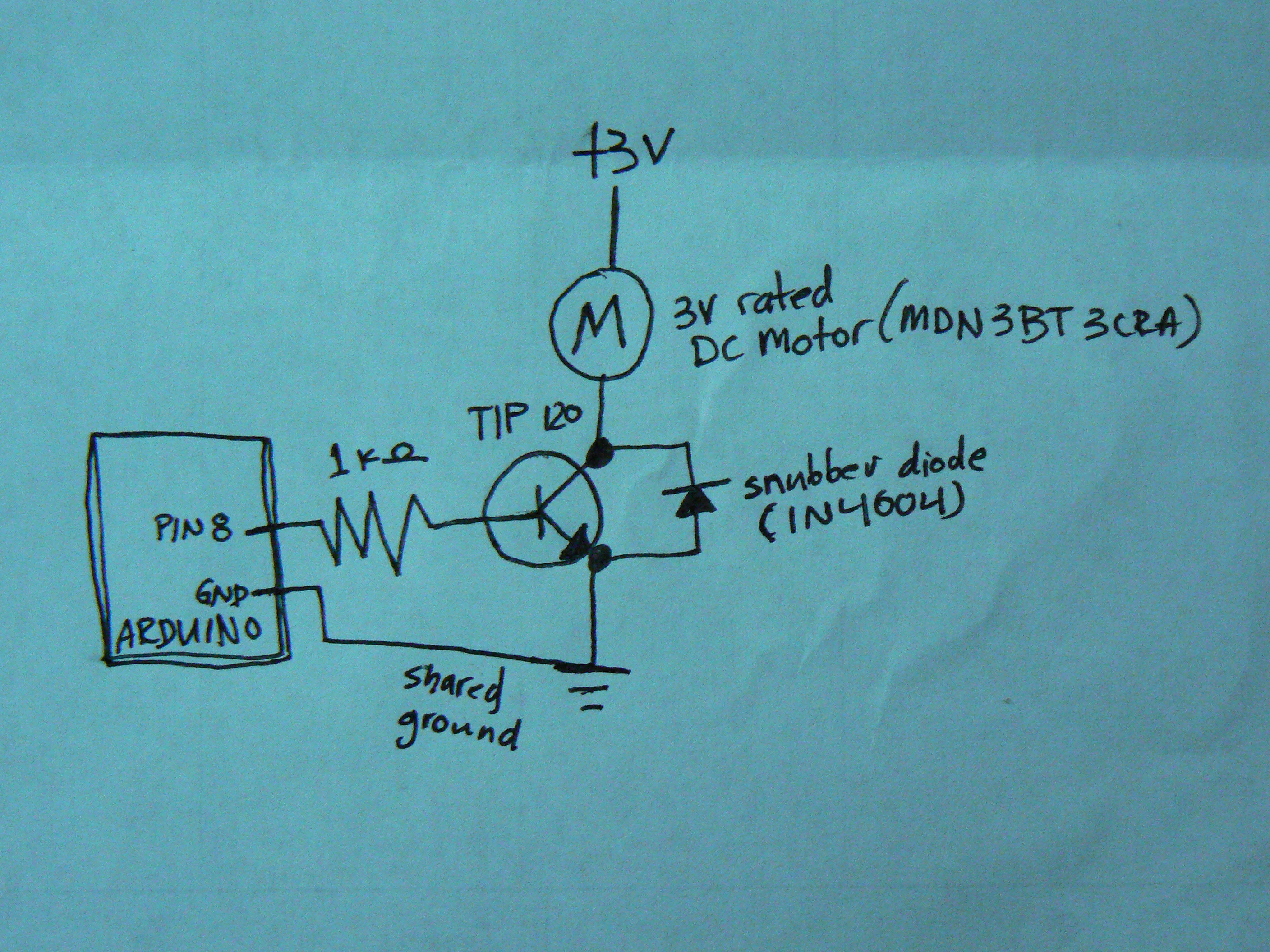
When controlling motors with a microcontroller, the snubber is quite important. This configuration is not commonly seen, as the snubber is typically placed across the motor itself. The general concept is that charge builds up on the motor coil,...
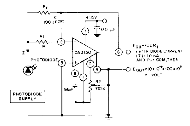
The photodiode current-to-voltage converter circuit employs three CA3130 BiMOS operational amplifiers, designed for applications that require sensitivity to sub-picoampere input currents. This circuit generates a ground-referenced output voltage that is directly proportional to the input current flowing through the...
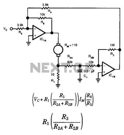
This circuit provides bidirectional speed regulation for small motors and does not require a tachometer. The voltage applied to the motor's windings, which is determined by summing amplifier IC1A, is expressed as a function of the command voltage (Vc)...
Warning: include(partials/cookie-banner.php): Failed to open stream: Permission denied in /var/www/html/nextgr/view-circuit.php on line 713
Warning: include(): Failed opening 'partials/cookie-banner.php' for inclusion (include_path='.:/usr/share/php') in /var/www/html/nextgr/view-circuit.php on line 713