
Hc-based-oscillators
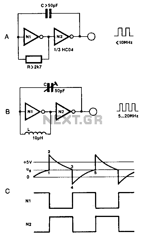
Two inverters, one resistor, and one capacitor are sufficient to create an HC(T)-based oscillator that operates reliably up to approximately 10 MHz. The use of two HC inverters results in a fairly symmetrical rectangular output signal. In this configuration, HCT inverters yield a duty cycle of about 25%, as opposed to around 50%, because the toggle point of an HC inverter is 1/2 Vee, while that of an HCT inverter is slightly less than 2 V. If the oscillator is intended to function above 10 MHz, the resistor is substituted with a small inductor, as illustrated in Figure 68-4B. The output frequency of the circuit in Figure 68-4A is approximately 1/(1.8 Rc), and it can be adjusted by connecting a 100 kΩ potentiometer in series with R. The solution for the oscillator in Figure 68-4B is even more straightforward, utilizing a 50 pF trimmer capacitor.
The described oscillator circuit utilizes two inverters, typically CMOS types, to generate a stable output frequency. The choice of HC(T) inverters is crucial, as they offer low power consumption and high-speed operation, making them suitable for frequencies up to 10 MHz. The symmetrical rectangular waveform generated by the inverters ensures that the output can be used for various applications requiring clock signals or timing references.
In the standard configuration, the duty cycle is influenced by the characteristics of the inverters. HCT inverters are preferred when a lower duty cycle is necessary for specific applications, as their toggle point characteristics lead to a duty factor of approximately 25%. This can be advantageous in digital circuits where specific timing requirements must be met.
For operation beyond 10 MHz, replacing the resistor with a small inductor allows the circuit to maintain stability at higher frequencies. The inductor introduces a different phase relationship between the voltage and current, which can enhance the oscillator's performance at these frequencies. The output frequency relation of 1/(1.8 Rc) indicates that the frequency is inversely proportional to the capacitance and resistance, allowing for fine-tuning through the addition of a variable resistor (potentiometer). This potentiometer provides the ability to adjust the frequency dynamically, making the circuit versatile for various applications.
The use of a trimmer capacitor in the higher frequency configuration simplifies the design further while allowing for precise adjustments to the capacitance value. This is particularly useful in applications where fine-tuning of frequency is critical, such as in RF circuits or timing applications in digital systems. The combination of these components in a compact design leads to an efficient and reliable oscillator circuit suitable for a range of electronic applications.Two inverters, one resistor, and one capacitor are all that is required to make a HC(T)-based oscillator that gives reliable operation up to about 10 MHz. The use of two HC inverters produces a fairly symmetrical rectangular output signal. In the same circuit, HCT inverters give a duty factor of about 25%, rather than about 50%, since the toggle point of an HC and an HCT inverter is 1 /z Vee, and slightly less than 2 V, respectively.
If the oscillator is to operate above 10 MHz, the resistor is replaced with a small inductor, as shown in Fig. 68-4B. The output frequency of the circuit in Fig. 684A is given as about 1/l.Brc, and can be made variable by connecting a 100-KO potentiometer in series with R.
The solution adopted for the oscillator in Fig. 68-4B is even simpler: C is a 50-pF trimmer capacitor. 🔗 External reference
Warning: include(partials/cookie-banner.php): Failed to open stream: Permission denied in /var/www/html/nextgr/view-circuit.php on line 713
Warning: include(): Failed opening 'partials/cookie-banner.php' for inclusion (include_path='.:/usr/share/php') in /var/www/html/nextgr/view-circuit.php on line 713