
Head phone amplifier circuit

The headphone amplifier circuit operates by first amplifying the weak audio signal from the music player using the Q1 transistor. The BC 239 transistor is configured as a common emitter amplifier, which provides voltage gain. The input audio signal is applied to the base of Q1, and the amplified output is taken from the collector. The feedback mechanism through resistor R3 is crucial as it stabilizes the gain and reduces harmonic distortion, leading to a cleaner audio output.
Following the preamplification stage, the output signal is sent to the driver stage formed by Q2 and Q3 transistors. The BC 337 and BC 327 transistors are configured in a push-pull arrangement, allowing for efficient driving of the headphones. This configuration helps to deliver the necessary current to the headphones, ensuring that they are adequately powered for optimal sound reproduction.
The power supply for this circuit should be carefully selected to match the voltage requirements of the transistors, typically ranging from 9V to 12V. Proper bypass capacitors should be included to filter out any power supply noise, ensuring that the amplifier delivers a clean audio signal.
Overall, this headphone amplifier circuit is an effective solution for enhancing audio output from devices that may not provide sufficient power, utilizing a minimal number of components while achieving high performance.Here is a simple head phone amplifier circuit that can be used to drive your head phone if your music player doesn`t have enough power to drive your head phones. The circuit is straight forward and uses only three transistors. The transistor Q1 (BC 239) and associated components forms a pre amplifier. The transistor pairs Q2 & Q3 (BC 337 & BC 327) f orms the driver circuit for the speaker. Power amplification is attained at this stage. The emitter voltage of Q1 is fed back to base of Q1 via R3 in order to improve performance and reduce distortion. 🔗 External reference
Related Circuits

A simple technique for measuring frequencies across a wide range with acceptable accuracy limits using a PC is presented. This method follows the basic principle of measuring low frequencies, where the period of a complete wave is measured and...
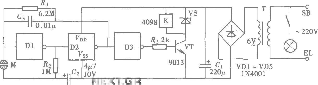
A CMOS gate exhibits high input impedance, which allows it to respond to changes in input levels due to human contact, thereby triggering the toggling of gates. The circuit utilizes this characteristic to create a touch lamp switch. The...
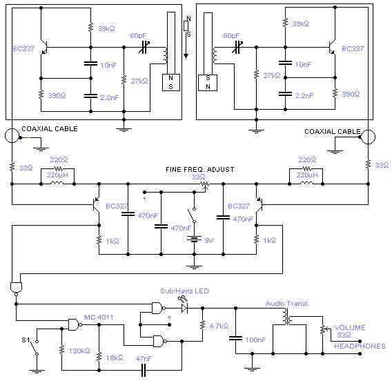
This is a rather sensitive circuit which will detect minute variations of a magnetic field, particularly the Earth magnetic field. The principle is based on an audio beat tone generated by two identical oscillators. These must be built in...

This design circuit functions as an alarm system controlled by a keypad. The core component of the circuit is a single transistor from the BC547 series. The circuit requires a 12-key pad, which has 13 terminals; a matrix type...
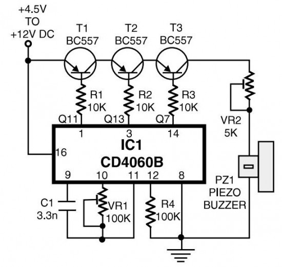
The circuit generates pulses of 1.25 Hz from pin 1 and 20 Hz from pin 14. The three output pins of IC1 are connected to the base terminals of transistors T1, T2, and T3 through resistors R1, R2, and...

A voltage comparator is a device that compares the voltages at its two inputs and generates an output based on the comparison. It produces a high output when the positive input exceeds the negative input and a low output...
Warning: include(partials/cookie-banner.php): Failed to open stream: Permission denied in /var/www/html/nextgr/view-circuit.php on line 713
Warning: include(): Failed opening 'partials/cookie-banner.php' for inclusion (include_path='.:/usr/share/php') in /var/www/html/nextgr/view-circuit.php on line 713