
Headlight-alarm
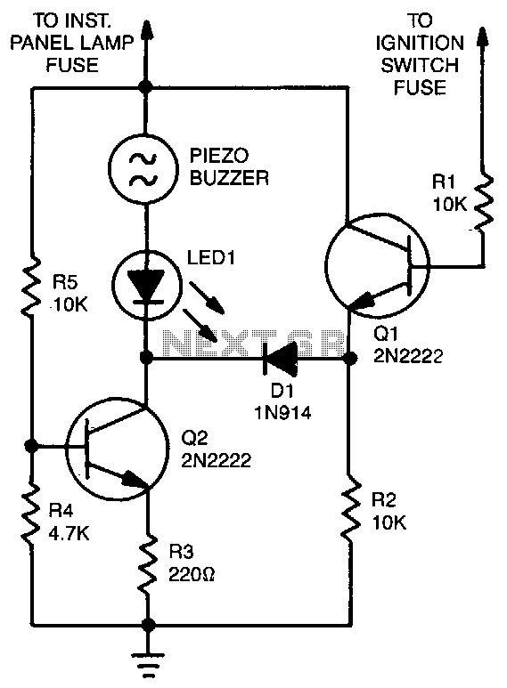
The base of Q1 is connected to the car's ignition circuit. One side of the piezoelectric buzzer is connected to the instrument panel light fuse. When the headlights are off, no current reaches the buzzer, and therefore nothing happens. When the headlights are on, the outcome depends on the state of the ignition switch. When the ignition switch is on, transistors Q1 and Q2 are biased on, removing the buzzer and the LED from the circuit. When the ignition switch is turned off, but the headlight switch remains on, transistor Q1 is turned off, but transistor Q2 continues to be biased on. The result is that the voltage is sufficient to sound the buzzer loudly and light the LED. Turning off the headlight switch will end the commotion quickly.
The described circuit functions as a warning system integrated into a vehicle's electrical system, utilizing transistors and a piezoelectric buzzer to indicate the status of the headlights in relation to the ignition switch.
In this circuit, transistor Q1 serves as a control switch that is activated by the ignition circuit. When the ignition is on, Q1 is biased, allowing current to flow through both Q1 and Q2. This condition effectively removes the piezoelectric buzzer and the LED from the circuit, preventing any sound or light indication.
Conversely, when the ignition switch is turned off while the headlights remain on, Q1 ceases to conduct, but Q2 remains biased due to the voltage present from the headlight circuit. This configuration allows sufficient voltage to activate the piezoelectric buzzer, producing an audible alert, while also illuminating the LED as a visual warning.
The piezoelectric buzzer is connected to the instrument panel light fuse, which provides power to the buzzer only when the headlights are engaged. The LED serves as an additional indicator, providing a visual cue in conjunction with the audio alert.
To deactivate the alert system, the operator must turn off the headlight switch, which interrupts the voltage supply to Q2, thus silencing the buzzer and extinguishing the LED. This design ensures that the driver is informed when the headlights are left on after the ignition has been switched off, reducing the risk of draining the vehicle’s battery.
Overall, this circuit exemplifies a practical application of transistors in automotive electronics, enhancing driver awareness and safety.The base of Ql is connected to the car"s ignition circuit. One side of the piezoelectric buzzer is connected to the instrument-panellight fuse. When the headlights are off,. no current reaches the buzzer, and therefore nothing happens. What happens when the headlights are on depends on the state of the ignition switch. When the ignition switch is on, transistors Ql and Q2 are biased on, removing the buzzer and the LED from the circuit. When the ignition .switch is turned off, but the headlight switch remains on; transistor Ql is turned off, but transistor Q2 continues to be biased on. The result is that the voltage is sufficient to sound the buzzer loudly and light the LED. Turning off the headlight switch will end the commotion quickly. 🔗 External reference