
Headlight Switch Wiring
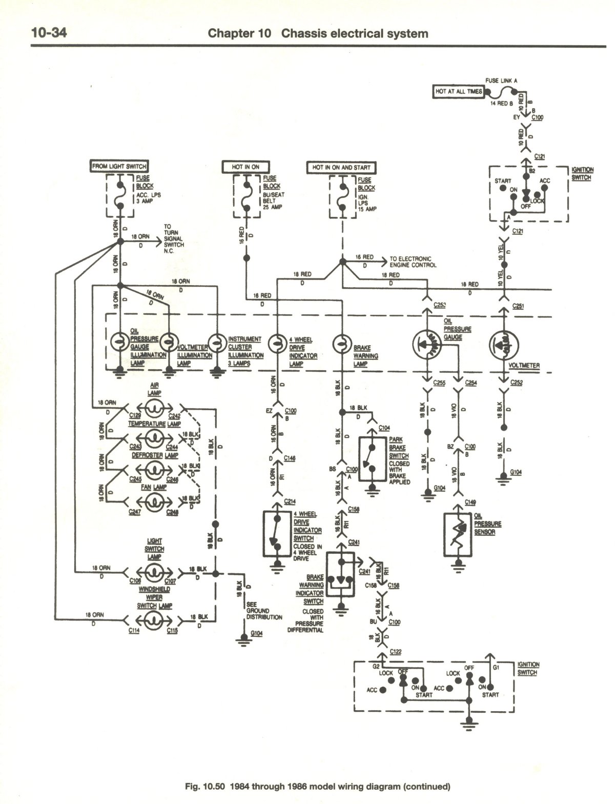
In automotive electrical systems, terminal connections play a crucial role in the functionality of various components. Terminal 66 RED is typically associated with the dash light dimmer circuit, which adjusts the brightness of the dashboard lights. If no output is observed at this terminal, troubleshooting is essential to identify the cause of the malfunction.
One possible reason for the lack of output could be that the dash light dimmer is inadvertently turned to the "OFF" position. This is a straightforward issue that can be resolved by simply adjusting the dimmer control to a higher setting.
Alternatively, if the dimmer is correctly set, the problem may lie within the rheostat itself. The rheostat is a variable resistor that controls the current flowing to the dashboard lights. Over time, exposure to moisture and other environmental factors can lead to corrosion on the rheostat's wiper, which is the contact point that adjusts the resistance. If corrosion is present, it can disrupt the electrical connection, resulting in no output at terminal 66 RED.
To diagnose this issue, it is advisable to inspect the rheostat for any signs of corrosion or damage. Cleaning the contact points with an appropriate electrical contact cleaner may restore functionality. If the rheostat is severely corroded or damaged, replacement may be necessary to ensure proper operation of the dashboard lighting system.
In summary, when troubleshooting terminal 66 RED, it is essential to check both the position of the dash light dimmer and the condition of the rheostat to determine the root cause of the issue.if you are not getting anything at 66 RED then that is a problem. You could have your dash light dimmer turned to the "OFF" position. Or the corrosion on the wiper for the rheostat could be so bad it can`t make contact. 🔗 External reference
Related Circuits
VD represents the voltage drop across the diode, while VTrans indicates the voltage drop across the transistor. The boundary between continuous and discontinuous operation occurs when the output current (io) is zero. A primary consideration in converter design is...
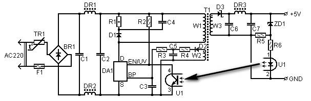
5 Volt/1.5A Switching Power Supply based on the TNY264P power supply. Refer to the designated page for an explanation of the related circuit diagram. The 5 Volt, 1.5A switching power supply utilizing the TNY264P is a compact and efficient power...
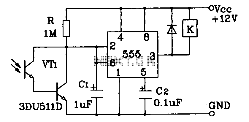
Darlington phototransistor type light-sensitive switch control circuit application. The Darlington type phototransistor serves as a sensitive element, capable of detecting low light levels for the detection of reflected light signals. The Darlington phototransistor circuit utilizes a pair of transistors configured...

1998 Ford Escort Blower Motor Wiring Diagram. The 1998 Ford Escort blower motor wiring diagram provides essential information for understanding the electrical connections and components involved in the operation of the vehicle's heating and ventilation system. This diagram typically...
This is a single-channel (on/off) universal switch that can be used with any infrared remote control operating within wavelengths of 850-950 nm. The single-channel universal switch functions as a simple on/off control mechanism, allowing users to operate electronic devices remotely...
Thank you very much. I will try that. @StevanC, what do you think? Are we making some progress, or should we stick to your design, ScratchRobot? The provided text appears to be a conversation regarding the evaluation of progress on...