
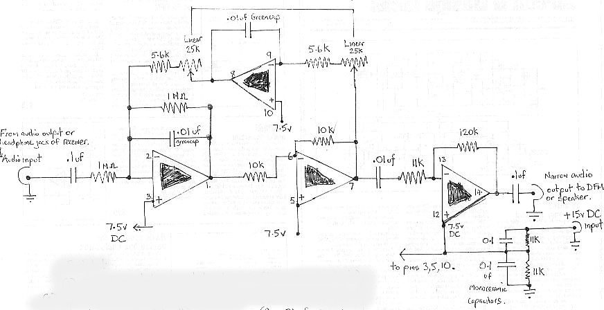
Headphone Audio Amplifier with Balance Control
This audio amplifier circuit features a symmetrical design, with both halves mirroring each other to ensure consistent performance across left and right channels. The inclusion of a dual logarithmic potentiometer for input control allows for precise adjustments, accommodating varying input levels. The balance control, implemented as a linear potentiometer, facilitates fine-tuning of signal levels between channels, enhancing the user experience by allowing for personalized audio balance.
The use of 10k resistors at the inputs serves a critical protective function, safeguarding against accidental short circuits to ground, which could otherwise damage the circuit or lead to malfunction. The common emitter amplifier stage is responsible for the initial amplification of the audio signal, characterized by a moderate gain that is sufficient for typical headphone applications. Following this, the emitter follower configuration provides a low-output impedance, enabling the circuit to drive headphones effectively.
The design accommodates 8-ohm headphones, which are common in consumer audio applications, while also supporting higher impedance headphones, making it versatile for various listening scenarios. The 2.2k output resistors play a vital role in maintaining signal integrity by blocking any DC offset that may arise from the coupling capacitors, thereby preventing disruptive sounds when headphones are connected or disconnected.
The self-biasing nature of the circuit simplifies its operation, allowing it to function across a wide range of DC power supply voltages, from 6 to 20 volts. This flexibility makes the circuit suitable for diverse applications, from portable audio devices to more stationary setups. Overall, the design emphasizes reliability, user control, and compatibility with standard audio equipment, making it an effective solution for audio amplification needs.Both halves of the circuit are identical. Both inputs have a dc path to ground via the input 47k control which ought to be a dual log type potentiometer. The balance control is a single 47k linear potentiometer, which at middle modification prevents even attenuation to both left and right input signals.
If the balance control is moved towards the left side, the left input track has less resistance than the right track and the left channel is reduced more than the right side and vice versa. The earlier 10k resitors be definite that neither input can be "shorted" to earth. Amplification of the audio signal is provided by a single stage common emitter amplifier and then via a direct coupled emitter follower.
Overall gain is less than 10 but the final emitter follower stage will directly drive 8 ohm headphones. Higher impedance headphones will work equally well. Note the final 2k2 resistor at each output. This removes the dc potential from the 2200u coupling capacitors and prevents any "thump" being heard when headphones are plugged in.
The circuit is self biasing and designed to work with any power supply from 6 to 20 Volts DC. 🔗 External reference
Related Circuits
Our present car controller runs on a single PIC16F870 micro and provides functions for remote door locks, headlight reminder, and car finder. It is constructed using wire-wrap to allow for future expansion and is mounted using Velcro on the...
The compact, low-cost condenser microphone audio amplifier described here provides high-quality audio output of 0.5 watts at 4.5 volts. It can be utilized in intercom systems, walkie-talkies, low-power transmitters, and packet radio receivers. Transistors T1 and T2 constitute the...
This circuit employs an 87C57 microcontroller along with several peripherals to convert X-10 power-line carrier-code formats from a personal computer for use with an X-10 power-line interface in a home-control system. Software details can be found in the reference. The...
The audio bandpass filter described is beneficial for amplifying and filtering weak AM TV video carriers. For instance, a digital frequency audio multimeter (DFM) may lack sufficient input sensitivity for measuring extremely weak single sideband (SSB) TV video audio...
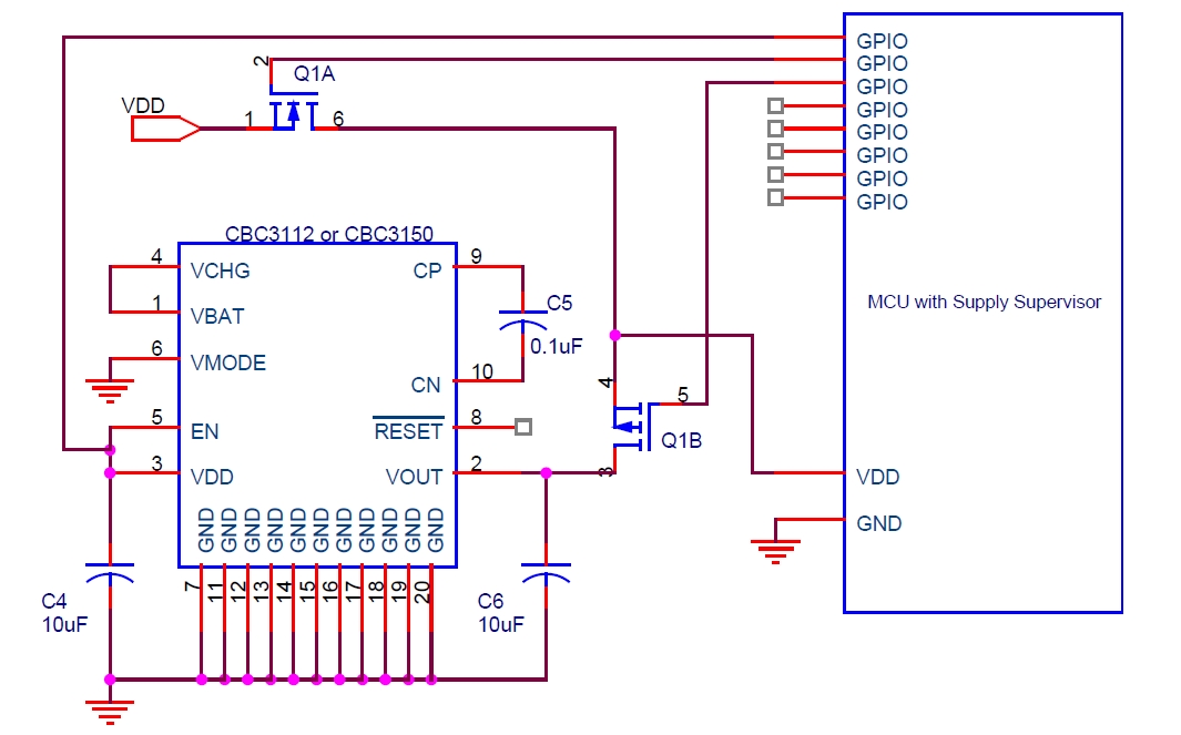
Cymbet Corporation provides rechargeable solid-state batteries designed for advanced microcontroller power backup applications. The company is recognized as a leader in thin-film energy storage technology. Cymbet Corporation's rechargeable solid-state batteries are engineered to deliver reliable power solutions for microcontrollers, which...
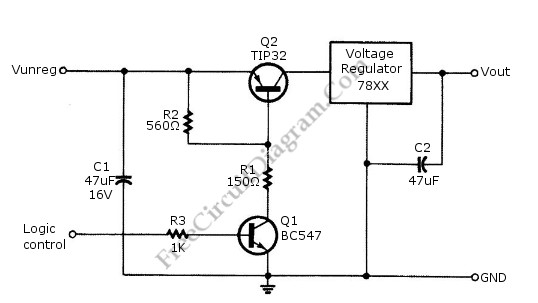
Logic power control of an analog regulator can be useful in applications where a digital circuit or controller needs to manage a power source, such as in EEPROM programmers or other power control systems. This circuit provides ON-OFF control...
Warning: include(partials/cookie-banner.php): Failed to open stream: Permission denied in /var/www/html/nextgr/view-circuit.php on line 713
Warning: include(): Failed opening 'partials/cookie-banner.php' for inclusion (include_path='.:/usr/share/php') in /var/www/html/nextgr/view-circuit.php on line 713