
Heartbeat Monitor Circuit with LED and Photocell
The circuit design incorporates a light screen formed by an LED emitter and a photocell, which are aligned to create a detection zone. When a finger enters this zone, it interrupts the light path, causing variations in the light intensity detected by the photocell. The photocell converts these light intensity changes into an electrical signal, which corresponds to the heartbeat.
The output signal from the photocell is typically weak and may require amplification for effective processing. An operational amplifier (op-amp) can be utilized to boost the signal strength. The amplified signal is then fed into the analog input of the PIC16F84 microcontroller. The microcontroller is programmed to interpret the incoming signal, filtering out noise and identifying the peaks corresponding to each heartbeat.
Once the heartbeat signal is processed, the microcontroller calculates the heart rate, usually expressed in beats per minute (BPM). This calculated value is then sent to three common cathode seven-segment displays. Each display is controlled by the microcontroller, which manages the multiplexing necessary to show the heart rate in a clear and readable format.
For optimal performance, the circuit may include additional components such as resistors for current limiting, capacitors for signal smoothing, and possibly a diode for reverse polarity protection. The layout of the circuit should ensure minimal interference and maintain the integrity of the signal from the photocell to the microcontroller. Proper grounding and power supply decoupling are also essential to enhance the reliability of the heart rate monitoring system.the finger, inside a light screen, between an high intensity led emitter and a photocell, provides the heartbeat signal, which, suitably amplified, is used as input for a microcontroller PIC16F84. Three 7 segments common cathode displays, drived by the PIC, show the heart rate. 🔗 External reference
Related Circuits
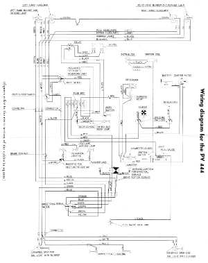
The following circuit illustrates the wiring diagram for the Volvo PV444, a vintage car electrical circuit. It provides an electrical understanding of this uni-body vehicle. The Volvo PV444 wiring diagram serves as a crucial reference for understanding the electrical system...
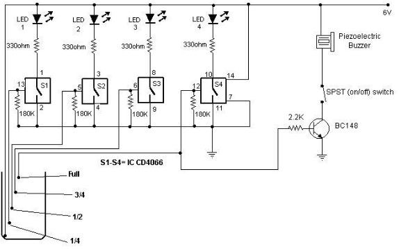
A simple and cost-effective water level indicator circuit can be designed using this schematic. This water level indicator utilizes a CMOS IC CD4066 to indicate the amount of water present in an overhead tank and to provide an alarm...
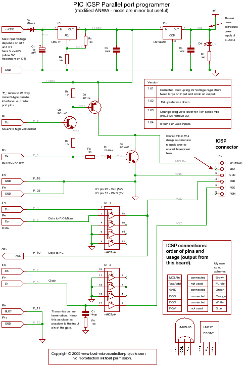
A PIC programmer circuit that operates using long cables from a PC to the programmer. The PIC programmer circuit is designed to facilitate the programming of PIC microcontrollers via a connection to a personal computer (PC) using extended cabling. This...
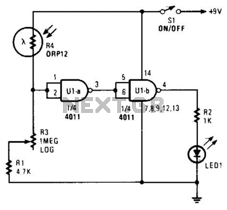
Two gates of a 4011 IC are utilized as a comparator. When the resistance of R4 decreases, the voltage at pins 1 and 2 increases, resulting in a logic zero at pin 3. This causes pin 4 to go...
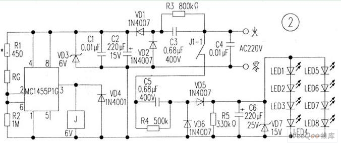
The circuit is depicted in Figure 1, while the electrical schematic diagram is presented in Figure 2. The AC voltage of 220V is reduced by components C3 and R3. The diodes VD1 and VD2 rectify the voltage, and capacitors...
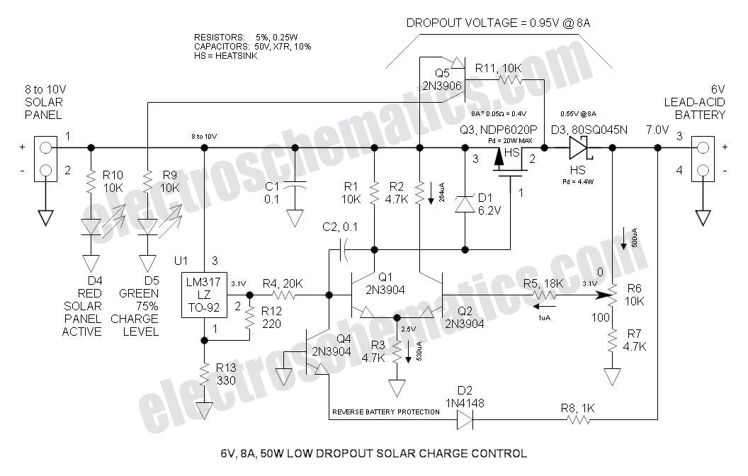
This Low Dropout Voltage (LDO) solar charge controller utilizes a straightforward differential amplifier combined with a series P-channel MOSFET linear regulator, ensuring compatibility and efficiency in solar energy applications. The Low Dropout Voltage (LDO) solar charge controller is designed to...