Heat Sensitive Switch

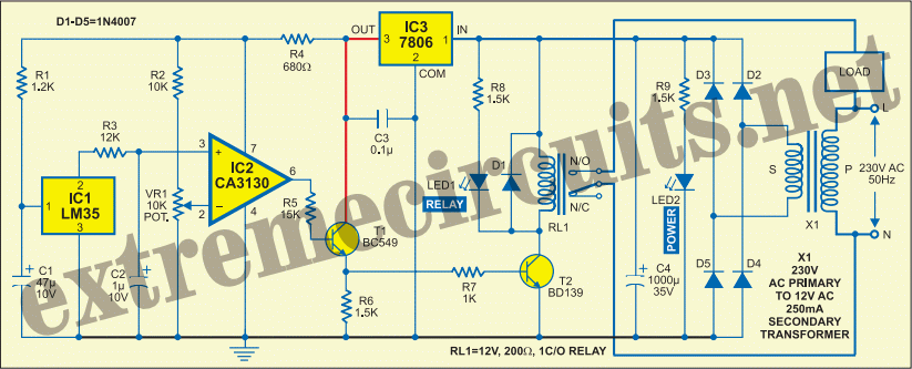
The core component of this heat-sensitive switch is the LM35 integrated circuit (IC1), which functions as a linear temperature sensor and temperature-to-voltage converter. This converter delivers an output signal that is accurately linear and directly proportional in millivolts across a temperature range of 0 °C to 155 °C, producing an output voltage of 10 mV for each degree Celsius change in temperature. Consequently, the output voltage spans from 0 mV at 0 °C to 1 V at 100 °C, allowing any connected voltage measurement circuit to read the temperature directly. The input and ground pins of this heat-to-voltage converter IC are connected to regulated power supply rails and are decoupled by resistor R1 and capacitor C1. The temperature output is fed into the non-inverting input (pin 3) of a comparator built using IC2. The inverting input (pin 2) of IC2 is connected to the positive supply rails through a voltage divider network created by potentiometer VR1. This configuration allows the voltage at the inverting input to be adjusted linearly. This voltage serves as the reference level for the comparator, compared against the output from IC1. If the voltage at the non-inverting input of IC2 is lower than the reference level, the output drops low (approximately 650 mV), which is then applied to the load-relay driver comprising NPN transistors T1 and T2. The low output at the base of transistor T1 keeps it in a non-conductive state, which also prevents T2 from conducting because it receives forward bias voltage through the emitter of T1. As a result, relay RL1 remains de-energized, keeping the mains supply to the load disconnected as long as the temperature detected by the sensor is low. Conversely, if the voltage at the non-inverting input exceeds the reference level, the output of IC2 rises high (approximately 2200 mV), activating the load. This occurs when IC1 detects a higher temperature, resulting in an increased output voltage that surpasses the reference level at the inverting input of IC2. Consequently, the load is powered on when the ambient temperature exceeds the predetermined threshold. Capacitor C3 connected at this pin mitigates any ripple from the positive supply rail, ensuring stable circuit operation. By adjusting potentiometer VR1 and thus varying the reference voltage at the inverting input of IC1, the temperature threshold for energizing the relay can be set. This adjustment is linear, allowing the potentiometer's knob to be fitted with a calibrated linear dial in degrees Celsius. This enables the selection and continuous monitoring of any temperature level for external actions, such as activating a room heater in winter or a room cooler in summer. The circuit can also be adapted to trigger emergency fire extinguishers when placed at potential fire hazard locations. Modifications can be made to operate any electrical appliance, requiring relay RL1 to be a heavy-duty type with suitably rated contacts to meet the power demands of the intended load.
The schematic includes several key components that ensure precise temperature monitoring and control. The LM35 temperature sensor (IC1) provides a reliable and linear output, which is critical for accurate temperature readings. The comparator IC (IC2) serves as a decision-making component, comparing the output from the LM35 with a user-defined reference voltage set by the potentiometer (VR1). The use of transistors (T1 and T2) as a relay driver is an effective method of controlling higher power loads, allowing for safe operation of devices that may draw substantial current. The inclusion of capacitors (C1 and C3) helps maintain signal integrity and stability, filtering out noise that could affect the performance of the circuit. The design is versatile, allowing for applications ranging from climate control to safety systems, and can be easily adapted to suit various operational requirements by selecting appropriate relay specifications and adjusting the reference voltage threshold.At the heart of this heat-sensitive switch is IC LM35 (IC1), which is a linear temperature sensor and linear temperature-to-voltage converter circuit. The converter provides accurately linear and directly proportional output signal in millivolts over the temperature range of 0 °C to 155 °C.
It develops an output voltage of 10 mV per degree centigr ade change in the ambient temperature. Therefore the output voltage varies from 0mV at 0 °C to 1V at 100 °C and any voltage measurement circuit connected across the output pins can read the temperature directly. The input and ground pins of this heat-to-voltage converter IC are connected across the regulated power supply rails and decoupled by R1 and C1.
Its temperature-tracking output is applied to the non-inverting input (pin 3) of the comparator built around IC2. The inverting input (pin 2) of IC2 is connected across the positive supply rails via a voltage divider network formed by potentiometer VR1.
Since the wiper of potentiometer VR1 is connected to the inverting input of IC2, the voltage presented to this pin is linearly variable. This voltage is used as the reference level for the comparator against the output supplied by IC1. So if the non-inverting input of IC2 receives a voltage lower than the set level, its output goes low (approximately 650 mV).
This low level is applied to the input of the load-relay driver comprising npn transistors T1 and T2. The low level presented at the base of transistor T1 keeps it nonconductive. Since T2 receives the forward bias voltage via the emitter of T1, it is also kept non-conductive. Hence, relay RL1 is in de-energised state, keeping mains supply to the load off` as long as the temperature at the sensor is low.
Conversely, if the non-inverting input receives a voltage higher than the set level, its output goes high (approximately 2200mV) and the load is turned on. ` This happens when IC1 is at a higher temperature and its output voltage is also higher than the set level at the inverting input of IC2.
So the load is turned on as soon as the ambient temperature rises above the set level. Capacitor C3 at this pin helps iron out any ripple that passes through the positive supply rail to avoid errors in the circuit operation. By adjusting potentiometer VR1 and thereby varying the reference voltage level at the inverting input pin of IC1, the temperature threshold at which energisation of the relay is required can be set.
As this setting is linear, the knob of potentiometer VR1 can be provided with a linear dial calibrated in degrees centigrade. Therefore any temperature level can be selected and constantly monitored for external actions like turning on a room heater in winter or a room cooler in summer.
The circuit can also be used to activate emergency fire extinguishers, if positioned at the probable fire accident site. The circuit can be modified to operate any electrical appliance. In that case, relay RL1 must be a heavy-duty type with appropriately rated contacts to match the power demands of the load to be operated.
🔗 External reference
Warning: include(partials/cookie-banner.php): Failed to open stream: Permission denied in /var/www/html/nextgr/view-circuit.php on line 713
Warning: include(): Failed opening 'partials/cookie-banner.php' for inclusion (include_path='.:/usr/share/php') in /var/www/html/nextgr/view-circuit.php on line 713


