
Heat Sensor Circuit
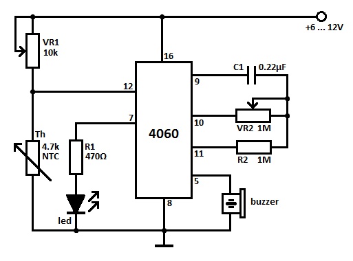
The first heat sensor circuit utilizing the 4060 IC is based on the principle of temperature detection through a thermistor or similar temperature-sensitive component. The 4060 IC functions as an oscillator, generating a frequency output that varies with temperature changes. The thermistor is connected to a resistor, forming a voltage divider that provides an input to the 4060. As the temperature increases or decreases, the resistance of the thermistor changes, thereby altering the voltage at the input of the IC. This change in voltage leads to a corresponding change in the frequency output, which can be monitored or used to trigger other components in the circuit, such as alarms or indicators.
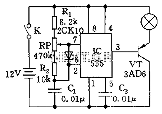
The second heat sensor circuit is designed to be more straightforward, likely employing a basic transistor or operational amplifier configuration to sense temperature changes. This circuit may use a thermistor directly connected to a comparator circuit, where the output changes state based on a predefined temperature threshold. Fewer components in this design make it easier to assemble and potentially more cost-effective, though it may lack some of the advanced features provided by the 4060-based circuit.
Both circuits can be utilized in various applications, such as temperature monitoring systems, fire detection systems, and HVAC controls, showcasing the versatility of heat sensing technologies in electronic design.Here are 2 heat sensor circuits, first one is build with the 4060 IC, the second one is simpler than the one before and has fewer components. It is an idea.. 🔗 External reference
Related Circuits
The circuit illustrated in the figure is a dimmer using the 555 timer as the core component. The 555 timer, along with resistors R1, RP, R2, and capacitor C1, forms an astable multivibrator. The oscillation frequency, f, is calculated...

This is a simple design schematic for a phase control circuit that regulates the power delivered to an AC load. The phase control circuit modifies the AC waveform, allowing for variations such as full cycle, half cycle, zero cycle,...
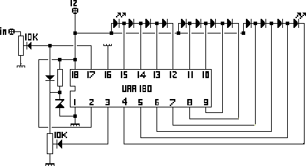
The NL3ASD schematic pages provide the schematics for a LED VU meter utilizing the UAA180 integrated circuit. The NL3ASD schematic pages feature a comprehensive design for a LED VU meter that employs the UAA180 IC, known for its audio signal...
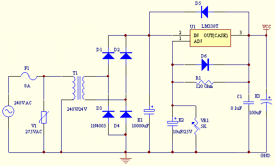
This project utilizes an LM338 adjustable three-terminal regulator to deliver a current of up to 5A with a variable output voltage ranging from 2V to 25V DC. It is particularly useful for powering various electronic circuits during the assembly...
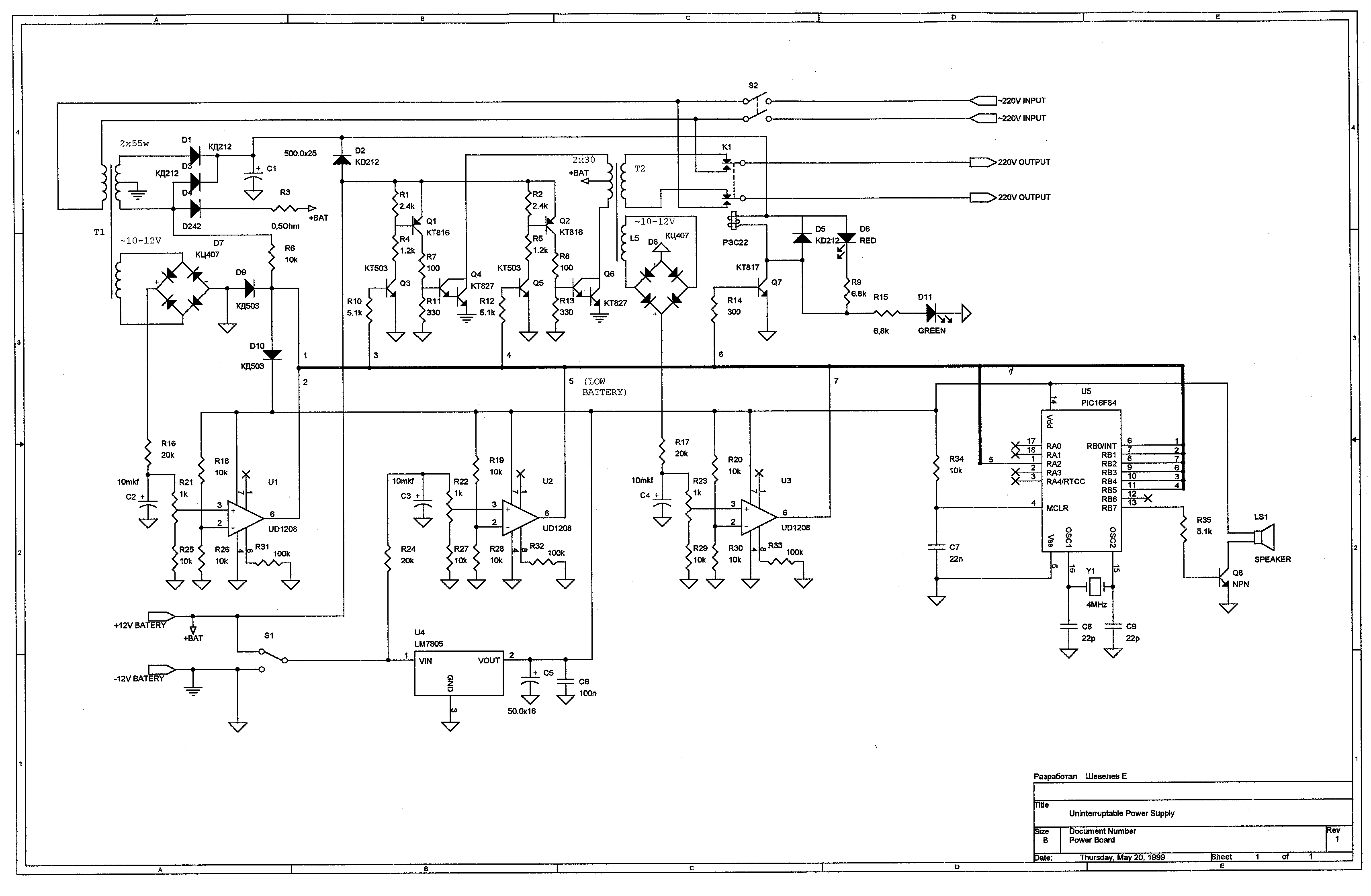
Full sine wave UPS information in English, along with detailed C language source code. English proficiency may be a concern, so caution is advised. A full sine wave Uninterruptible Power Supply (UPS) is designed to provide a stable and continuous...

This circuit is designed to convert continuously lit lamps into flashing lights. It can be easily integrated into an existing circuit by inserting it between the lamp and the negative supply. It is particularly suitable for use with car...