Hee-haw-slren

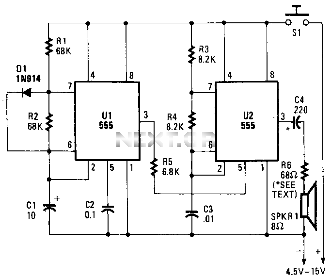
A pair of timer integrated circuits (ICs) form the core of a circuit designed to simulate the distinctive warbling sound of a British police siren. One of the 555 timers, designated as U2, is configured as an astable multivibrator that operates at approximately 900 Hz. The other timer, labeled U1, functions at around 1 Hz, generating a square wave output at pin 3 with a 50% duty cycle, resulting in on and off intervals of about 0.5 seconds each. The output from U1 is fed into pin 5, the control voltage terminal of U2. The frequency produced by the 555 timer IC is largely unaffected by supply voltage variations; however, it can be adjusted over a wide range by applying a variable voltage between pin 5 and ground. When the output from U1 goes high, U2 operates at approximately 800 kHz. This alternating between two frequencies creates the characteristic warbling hee-haw sound.
The circuit utilizes two 555 timer ICs, which are versatile and widely used in various applications due to their reliability and ease of use. The first timer, U1, operates as a low-frequency oscillator, generating a square wave signal at a frequency of approximately 1 Hz. This low-frequency output is critical as it controls the modulation of the second timer, U2. The modulation is achieved by connecting the output of U1 to the control voltage pin (pin 5) of U2, effectively allowing the lower frequency signal to influence the operation of the higher frequency oscillator.
U2, configured as an astable multivibrator, continuously switches between high and low states, producing a square wave output at around 900 Hz under normal conditions. However, the control voltage applied to pin 5 can modulate this frequency significantly. When the output of U1 transitions to a high state, it raises the control voltage at pin 5, causing U2 to shift its oscillation frequency closer to 800 kHz. This rapid switching between the two frequencies—900 Hz and 800 kHz—results in the desired warbling sound characteristic of a British police siren.
The design benefits from the inherent stability of the 555 timer IC, which allows for consistent frequency generation across varying supply voltages. The circuit can also incorporate additional components, such as capacitors and resistors, to fine-tune the frequency ranges or modify the duty cycle further, enabling customization for specific sound profiles. Overall, this circuit exemplifies the effective use of timer ICs in sound simulation applications, demonstrating both versatility and functionality in electronic design.A pair of timer IC"s are the heart of a circuit that simulates the warbling bee-haw of a British police siren. One of the 555 timers, U2, is wired as an astable multivibrator operating at about 900 Hz. The other, Ul, operates at approximately 1 Hz. Its output at pin 3 is a square wave with a 50% duty cycle-on and off cycles of about 0.5 second each.
The output of Ul is applied to pin 5, the control-voltage terminal of U2. The frequency of the 555 timer IC is relatively independent of supply voltage, but can be varied over a fairly wide range by applying a variable voltage between pin 5 and ground. When Ul "s output becomes high, U2 operates at about 800 kHz. That switching between two frequencies produces the warbling hee-haw signal.