
Hi-Fi Preamplifier
The circuit in question demonstrates a rapid response to high frequency inputs, as evidenced by the application of a 100kHz squarewave. This indicates that the circuit is capable of handling high-speed signals with minimal delay or distortion. The high-speed performance of this circuit is exceptional, suggesting that it may be suitable for applications requiring rapid signal processing, such as telecommunications, data transmission, or high-frequency electronics.
The use of Tina Pro for the production of all graphs implies that this circuit was designed and tested using professional-grade electronic design automation (EDA) software. EDA tools like Tina Pro facilitate the design, simulation, and verification of electronic circuits, enhancing their performance and reliability. This further attests to the high-quality design and execution of this circuit.
The origin of the circuit from Newtownabbey, Northern Ireland, does not directly impact the circuit's performance or characteristics, but it provides context about its development and the expertise of its designer. It is common practice in the field of electronics engineering to acknowledge the contributions of individuals or teams who have developed notable circuits, as it promotes a culture of innovation and continuous improvement.
In conclusion, this circuit exhibits a high frequency response, making it suitable for applications that require rapid signal processing. Its design and testing using Tina Pro indicate a professional approach to circuit design and a commitment to quality and performance.This circuit was submitted by Graham Maynard from Newtownabbey, Northern Ireland. It has an exceptionally fast high frequency response, as demonstrated by applying an 100kHz squarewave to the input. All graphs were produced using Tina Pro. 🔗 External reference
Related Circuits
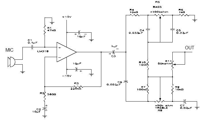
This simple microphone preamplifier is based on the LM318 operational amplifier. The LM318 operates as a standard non-inverting amplifier. Resistor R1 provides a ground input path for the bias current of the non-inverting input. The combination of R2 and...

The description refers to three circuits of the Recording Industry Association of America (RIAA), which are designed for the amplification of low signals from Moving Magnet (MM) heads. These circuits follow different solutions, each one concerning the equalization (eq). In...
The Stereo Tape Head Preamplifier kit is based on LA3161 IC from SANYO. Power supply - 9 ~ 12 VDC @ 20 mA. Output power - upto 200 mW. Input Resistance - 100 KΩ (Typ), Load Resistance - 10...
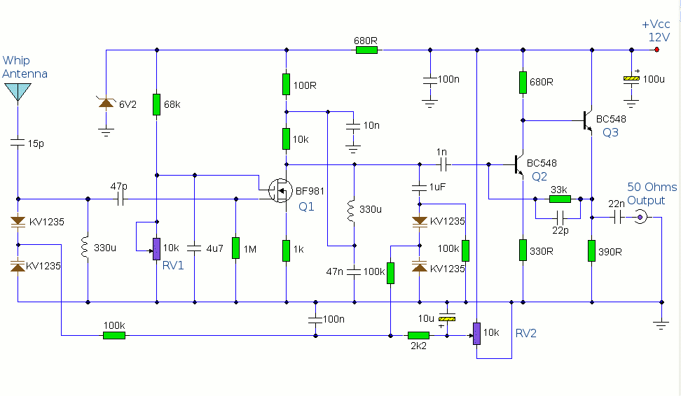
The antenna amplifier circuit comprises approximately 40 components, featuring two NPN transistors (BC548), one MOSFET (BF981), two varicap diodes (KV1235), and a 6.2V zener diode. It includes a 330µH inductor/coil, which can be modified for operation on different frequency...
This microphone preamplifier utilizes the low-noise integrated circuit (IC) uA739. The circuit serves as an example of an effective design for preamplifying dynamic microphones. The IC contains two operational amplifiers. The uA739 is a precision integrated circuit known for its...
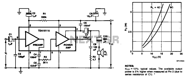
The monolithic integrated audio amplifier circuit is specifically designed for portable radio and recorder applications, delivering up to 4 W into a 4-ohm load impedance. The power output is close to 6 watts RMS. The monolithic integrated audio amplifier circuit...
Warning: include(partials/cookie-banner.php): Failed to open stream: Permission denied in /var/www/html/nextgr/view-circuit.php on line 713
Warning: include(): Failed opening 'partials/cookie-banner.php' for inclusion (include_path='.:/usr/share/php') in /var/www/html/nextgr/view-circuit.php on line 713