
Hi-Fi stereo Preamplifier with tone controls
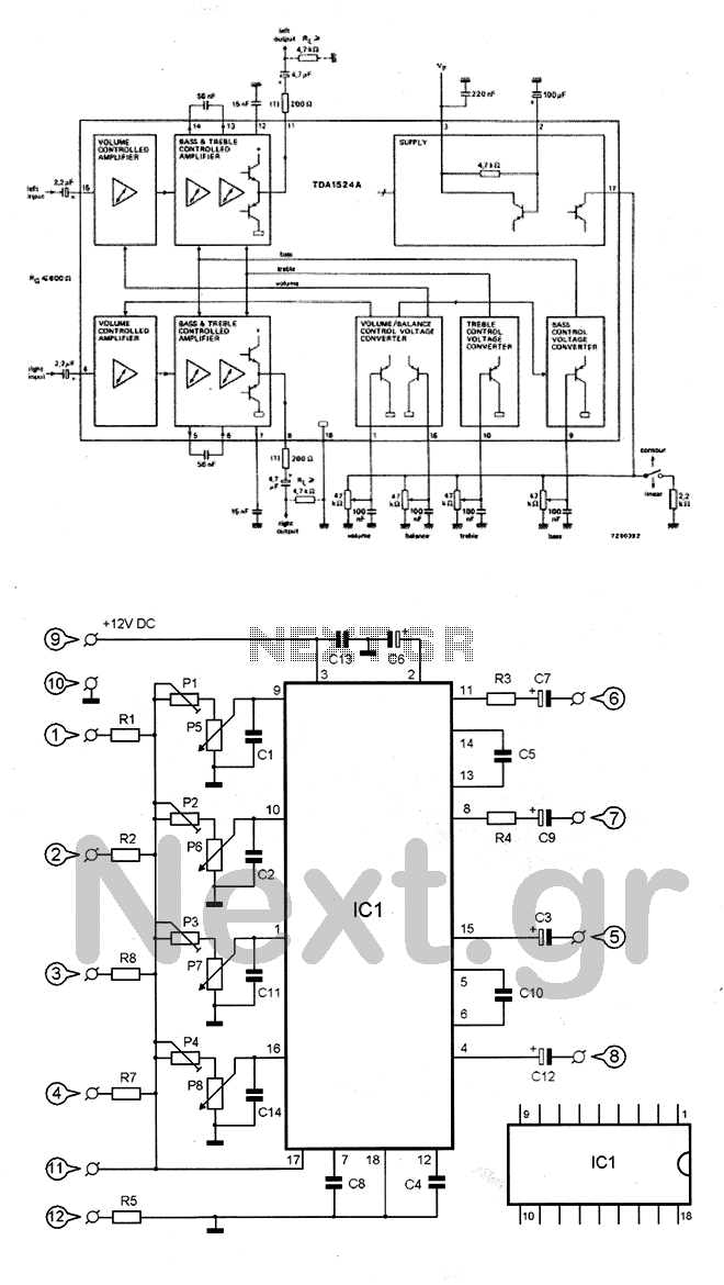
More: Potentiometer P5 adjusts the low frequencies (bass), while potentiometer P6 regulates the high frequencies (treble). Potentiometer P7 adjusts the volume, and potentiometer P8 controls the balance. Additionally, trimmers P1-P4 fine-tune various settings. When the volume (P7) is set to zero, the output is effectively zero. Similarly, when the two output signals are equal, the balance potentiometer (P8) is centered. The bass and treble knobs are also adjusted accordingly.
Parts and Components:
- R1, R2, R6, R7 = 82K 1/4W 5%
- R5 = 33K 1/4W 5%
- R3, R4 = 220 1/4W 5%
- P1-P4 = 22K Trimmer
- P5-P8 = 47K Potentiometers
- C1, C2, C11, C14 = 100nF Polyester Capacitors
- C3, C12 = 22uF/16V Electrolytic Capacitors
- C4, C8 = 15nF Polyester Capacitors
- C5, C10 = 56nF Polyester Capacitors
- C6 = 100uF/16V Electrolytic Capacitor
- C7, C9 = 4.7uF/16V Electrolytic Capacitors
- C13 = 220nF Polyester Capacitor
- IC1 = TDA1524 Chip
- IC Base = 18 DL
The TDA1524 is a versatile audio control IC that facilitates the adjustment of audio parameters in a compact design. The circuit is designed to optimize audio output quality by allowing precise control over bass, treble, volume, and balance. The use of potentiometers provides a user-friendly interface for real-time adjustments, making it suitable for various audio applications.
The input stage of the circuit is designed with careful consideration of component tolerances, ensuring that the input signal is accurately processed. The external components, including resistors and capacitors, are selected to maintain signal integrity and minimize noise. The arrangement of the input and output points facilitates easy integration with other audio components, enhancing the overall functionality of the circuit.
The optional remote control capability allows for additional convenience, enabling users to adjust settings from a distance. This feature is particularly beneficial in applications where the audio system is installed in a location that is not easily accessible.
Overall, the TDA1524-based circuit is a well-rounded solution for audio control, combining functionality with ease of use, making it an ideal choice for various audio systems.The circuit is based on the known chip TDA1524, which is an integrated control Volume, Bass, treble, and Balance. These arrangements are made through 4 potentiometers (P5-P8) with trend. The integrated circuit IC1, to run the needed very few external components. The potentiometer PI-P4 are used to compensate any tolerances POSTS components that regulate the input signal.
The input circuit is 5 points and 8 & 10 & 10. The output of the circuit is 7 points and 6 & 10 & 10. To supply to point 9 is a positive trend and 10 negative. Sections 1, 2, 3, 4, 11 and 15 are used for optional remote control circuit. The P5 potentiometer adjusts the low frequencies (BASS), while PO tensiometro P6 regulates high frequencies (TREBLE). Similarly, P7 potentiometer adjusts the volume (VOLUME) and the P8 BALANCE. Finally, the potentiometer P1 - P4 micrometer adjust various settings. So when the Volume (potentiometer P7) is positioned for zero output, the output is actually zero. Similarly, when the two output signals at the same level level, the potentiometer's Balance (P8) is in the middle.
Similarly, regulated and Bass and Treble knobs. Parts and Components: R1,R2,R6,R7=82K 1/4w 5% R5=33K 1/4W 5% R3,R4=220 1/4W 5% PI-P4=22K Trimmer P5-P8=47K Potentiometers C1,C2,C11,C14=100nF polyester C3,C12=22uF/16V electrolytic C4,C8=15nF polyester C5,C10=56nF polyester C6=100uF/16V electrolytic C7,C9=4,7uF/16V electrolytic C13=220nF polyester IC1=TDA1524 Chip IC base 18 DL 🔗 External reference
Related Circuits
The amplifier drives a pair of loudspeakers using two LM3876 integrated power amp ICs (50 watts per channel), or a pair of headphones via a Meier crossfeed filter and an OPA2134 dual opamp. It provides four switchable line level...
A challenging issue in the design of traditional stereo tone controls is achieving synchronized movement of the potentiometers. Even minor discrepancies in synchronization can lead to phase and amplitude variations between the two audio channels. Additionally, linear potentiometers are...
A unit that is often very useful for isolating two stages in sound circuits. This circuit includes an amplification unit with a gain of X1. Total negative feedback is not employed; instead, only local feedback is used, resulting in...
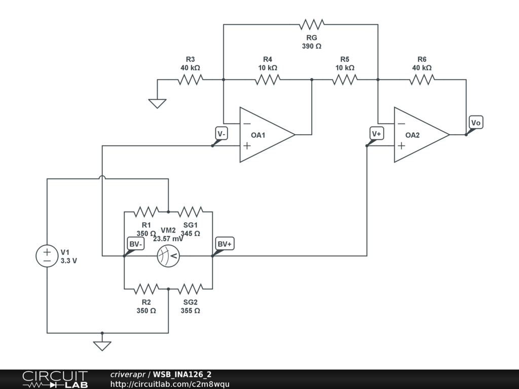
A half-bridge setup is utilized with strain gauges and an INA126 to amplify the voltage. The voltage can be read accurately when the lever is bent in one direction; however, no reading is obtained when the lever is bent...
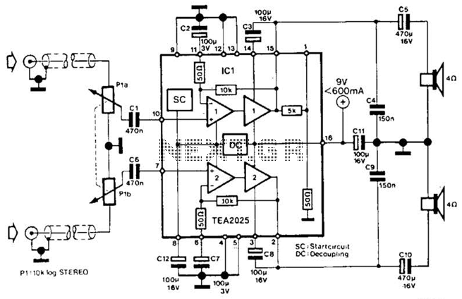
Using a Thomson TEA2025, this stereo amplifier delivers 1 W per channel into a 4-ohm load with a 9-V supply. The input sensitivity is 25 mV peak-to-peak for full output. It is important to ensure that pins 4, 5,...
This is a design for a tone control circuit. The circuit features the LM1036, which is a DC-controlled tone (bass/treble), volume, and balance circuit suitable for stereo applications in car radios, televisions, and audio systems. The LM1036 integrated circuit is...
Warning: include(partials/cookie-banner.php): Failed to open stream: Permission denied in /var/www/html/nextgr/view-circuit.php on line 713
Warning: include(): Failed opening 'partials/cookie-banner.php' for inclusion (include_path='.:/usr/share/php') in /var/www/html/nextgr/view-circuit.php on line 713