
High-Brightness LED-Driver
The high-brightness LED driver circuit is designed to efficiently manage the power supplied to LEDs, ensuring optimal performance and longevity. The circuit typically employs a constant-current source, which is crucial for LED operation, as variations in current can lead to significant changes in brightness and can even damage the LED.
The architecture of the circuit may include a DC/DC converter configured in either buck (step-down) or boost (step-up) mode, depending on the input and output voltage requirements. The circuit generally consists of a control loop that regulates the output current by adjusting the duty cycle of the PWM signal driving the switching element (usually a MOSFET). Feedback is obtained from a current-sensing resistor placed in series with the LED load, allowing for precise current regulation.
In addition, the circuit may incorporate protection features such as thermal shutdown, over-voltage protection, and short-circuit protection to enhance reliability. The use of high-frequency switching techniques allows for compact designs and minimizes heat generation, which is essential for high-brightness applications.
Moreover, the LED driver circuit can be designed to accommodate multiple LEDs in series or parallel configurations, depending on the desired output characteristics. The choice of components, such as inductors and capacitors, is critical and should be selected based on the operating frequency and load requirements to ensure stable operation.
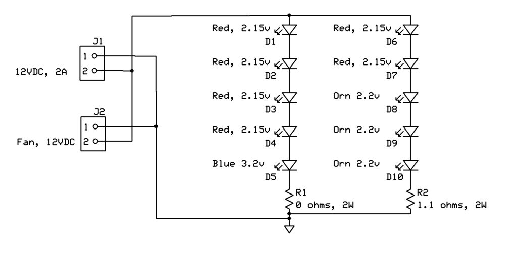
Overall, the implementation of a high-brightness LED driver circuit requires careful consideration of electrical parameters, component selection, and thermal management to achieve efficient and reliable LED illumination.This is a high-brightness LED-driver circuit. To provide a constant-voltage output we usually use DC/DC regulators. But constant-current output is the one that.. 🔗 External reference
Related Circuits

This application note discusses the use of SEPIC power modules to supply the necessary power for driving high-brightness LED arrays. These arrays serve as display backlights and necessitate a wide dimming range. The SEPIC configuration offers an efficient and...
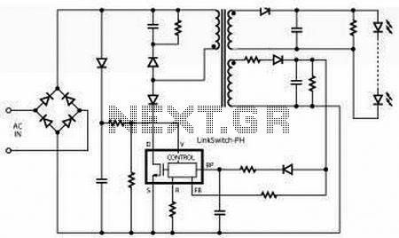
Power Integrations announced a new reference design (DER-278) based on the company's single-stage LinkSwitch-PH LED-driver IC family. The new design.. Power Integrations has introduced reference design DER-278, which utilizes the LinkSwitch-PH family of LED driver integrated circuits (ICs). This design...
This article discusses the design of an LED driver for automotive rear lights. It demonstrates that dimming is most effectively accomplished using pulse-width modulation (PWM) in conjunction with an LED driver integrated circuit (IC) that removes the requirement for...
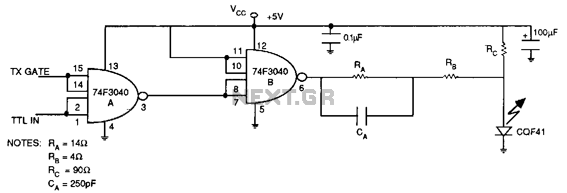
The pull-up transistor of the totem-pole output is used to turn on the LED, while the pull-down transistor is used to turn off the LED. The lower impedance and higher current handling capability of the saturated pull-down transistor serve...
This project page has evolved into a design discussion. Constructive suggestions and collaboration are still welcome. Please refer to the comments section. The project focuses on the development of an electronic circuit design, which has transitioned from a simple project...
Warning: include(partials/cookie-banner.php): Failed to open stream: Permission denied in /var/www/html/nextgr/view-circuit.php on line 713
Warning: include(): Failed opening 'partials/cookie-banner.php' for inclusion (include_path='.:/usr/share/php') in /var/www/html/nextgr/view-circuit.php on line 713