
High-efficiency-flyback-voltage-converter
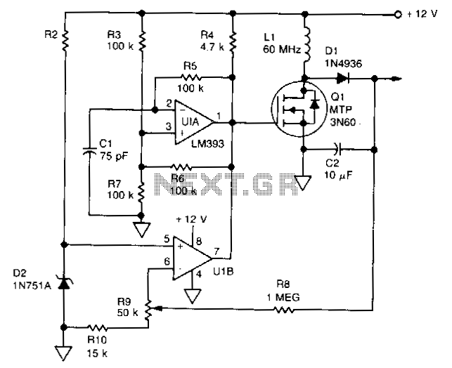
U1 is a dual voltage comparator with open collector outputs. The A side functions as an oscillator operating at 100 kHz, while the B side is part of the regulation circuit that compares a fraction of the output voltage to a reference generated by zener diode D2. The output of U1A is directly applied to the gate of Q1. During the positive half-cycle of the Q1 gate voltage, energy is stored in L1; during the negative half, the energy is discharged into C2. A portion of the output voltage is fed back to U1B to provide regulation. The output voltage is adjustable by changing the feedback potentiometer R9. Using the component values shown will produce a nominal 300 V output from a 12 V source. However, the circuit's maximum output voltage is limited by R10; a lower value for R10 yields a higher output voltage. The output voltage is also limited by the breakdown values of Q1, L1, D1, and C2.
The described circuit utilizes a dual voltage comparator, U1, with two distinct operational sides: an oscillator and a regulation circuit. The A side operates at a frequency of 100 kHz, generating a square wave signal that controls the switching of the transistor Q1. The open collector output from U1A directly drives the gate of Q1, allowing it to function as a switch that regulates current flow through the inductor L1.
During the positive half-cycle of the oscillation, Q1 is turned on, allowing current to flow through L1, which stores energy in the magnetic field. As the cycle transitions to the negative half, Q1 turns off, and the stored energy in L1 is released, charging the capacitor C2. This process is essential for maintaining a stable output voltage.
The feedback mechanism through U1B is crucial for the regulation of the output voltage. A fraction of the output voltage is fed back to U1B, where it is compared to the reference voltage generated by the zener diode D2. This comparison allows the circuit to adjust the output voltage dynamically. The feedback potentiometer R9 provides an adjustable means to set the desired output voltage, allowing for flexibility in various applications.
The circuit is designed to produce a nominal output of 300 V when supplied with a 12 V input. However, the maximum output voltage is constrained by the resistor R10, which acts as a limiting factor. Reducing the resistance of R10 will result in a higher output voltage, but this must be balanced against the breakdown ratings of the components involved, including Q1, L1, D1, and C2. These components must be selected carefully to ensure they can handle the maximum expected voltages and currents without failure.
Overall, this circuit exemplifies a well-designed voltage regulation system that efficiently converts a low input voltage into a higher output voltage while maintaining stability and providing adjustable output characteristics.Ul is a dual voltage comparator with open collector outputs. The A side is an oscillator operating at 100kHz, and the B side is part of the regulation circuit that compares a fraction of the output voltage to a reference generated by zener diode D2. The output of U1A is applied directly to the gate of Q1. During the positive half-cycle of the Q1 gate voltage, energy is stored in Ll; in the negative half, the energy is discharged into C2.
A portion of the output voltage is fed back to U1B to provide regulation. The output voltage is adjustable by changing feedback potentiometer R9. Using the component values shown will produce a nominal 300-V output from a 12-V source. However, the circuit maximum output voltage is limited by RlO; a lower value for R10 yields a higher output voltage. The output voltage is also limited by the breakdown of values Ql, L1, D1, and C2. 🔗 External reference
Warning: include(partials/cookie-banner.php): Failed to open stream: Permission denied in /var/www/html/nextgr/view-circuit.php on line 713
Warning: include(): Failed opening 'partials/cookie-banner.php' for inclusion (include_path='.:/usr/share/php') in /var/www/html/nextgr/view-circuit.php on line 713