
High frequency signal generator

The circuit described employs a tapped-coil Colpitts oscillator, which is a type of oscillator known for its stability and ability to produce a range of frequencies. The oscillator's tuning ranges, spanning from 1.7 to 31 MHz, are facilitated by the tapped coil configuration, which allows for different resonant frequencies to be accessed through adjustments in the coil taps. The inclusion of a Zener diode (D2) at Q1 is critical, as it regulates the voltage supplied to the oscillator, thereby enhancing its performance and reliability.
Capacitor C5 plays a vital role in coupling, ensuring that the oscillator operates efficiently without excessive loading on the tuned circuit. This careful coupling is essential for maintaining the oscillator's frequency stability and performance. Q2, acting as a source-follower buffer, provides impedance matching between the oscillator and the load, preventing any adverse effects on the oscillator's operation due to variations in load impedance.
RFC1, a radio frequency choke, is employed to tune the source of Q2, allowing for broader frequency adjustments and improving the overall response of the oscillator. This tuning is crucial for optimizing the performance of the oscillator across its specified frequency ranges.
The energy output from Q2 is fed into a feedback broadband class amplifier, which amplifies the signal while maintaining a wide bandwidth, ensuring that the oscillator's output remains consistent across its tuning ranges. The 2 dB attenuator at the output of T1 serves to match the output impedance to 50 ohms, which is a standard impedance for RF applications, thereby minimizing reflections and maximizing power transfer to subsequent stages.
Furthermore, the RF decoupling network formed by capacitors C16, C17, and RFC2 is essential for suppressing unwanted RF emissions. This network prevents the oscillator's energy from radiating into the environment, which could lead to interference with other electronic devices. By effectively isolating the oscillator from the 12 V supply, the circuit ensures cleaner operation and compliance with regulatory standards regarding electromagnetic interference. Overall, this design exemplifies careful consideration of component selection and circuit topology to achieve a reliable and effective oscillator circuit.A tapped-coil Colpitis oscillator is used at Ql to provide four tuning ranges from 1.7 to 3.131Hz, 3.0 to 5.6 MHz, 5.0 to 12 MHz and 11.5 to 31 MHz. A Zener diode (D2) is used at Ql to lower the operating voltage of the oscillator. A small value capacitor is used at C5 to ensure light coupling to the tuned circuit. Q2 is a source-follower buffer stage. It helps to isolate the oscillator from the generator-output load. The source of Q2 is broadly tuned by means of RFC1. Energy from Q2 is routed to a fed-back, broadband class- amplifier. A 2 dB attenuator is used at the output of Tl to provide a 50 ohm termination for Q3 and to set the generator-output impedance at 50 ohms. C16, C17 and RFC2 form a brute-force RF decoupling network to keep the generator energy from radiating outside the box on the 12 V supply.
🔗 External reference
Related Circuits
This sound frequency meter circuit is simple to build and can be constructed in a portable format. It can measure frequencies with a minimum level of 10 mV. The sound frequency meter circuit is designed to provide an effective and...
This is a high-efficiency emergency lamp that utilizes high-brightness white LEDs. It automatically activates during power failures and deactivates when power is restored. The emergency lamp circuit is designed to provide reliable illumination during power outages, utilizing high-brightness white LEDs...
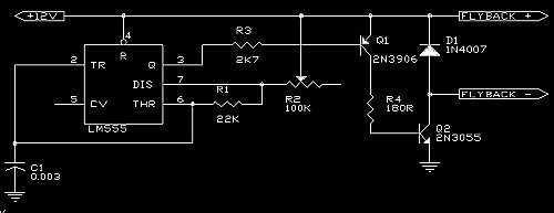
A 555 is used as an oscillator, optimally around 15.76KHz (in North America). Power pins on the chip (pin 1 to ground, pin 8 to +12V) are not shown on the diagram. The output from the 555 is then...

The CA3189 integrated circuit (IC) incorporates a symmetrical limiter, a phase demodulator, an audio amplifier, and a logarithmic detector-amplifier. The logarithmic detector-amplifier is particularly noteworthy for enhancing the logarithmic signal meter of shortwave receivers, thereby improving signal reading accuracy....

The basic connection circuit for the ISO103 signal and power supply is illustrated. Each power supply terminal must include a bypass filter. If the isolated power supply output current exceeds 15mA, it is advisable to utilize an external filter...
This is an antenna selector, preselector, attenuator, and preamplifier accessory designed for HF amateur transceivers. It enhances the receiver's IP2 for out-of-band signals and offers significant flexibility. The creators, enthusiasts of Amateur Radio, aim to optimize their equipment and...