
High impedance DC voltmeter
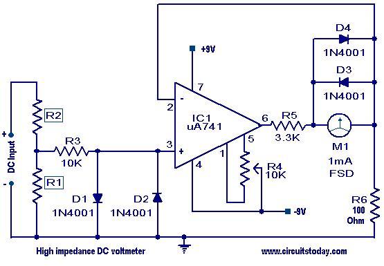
The high impedance DC voltmeter circuit designed around the uA741 operational amplifier is engineered for precision voltage measurements across a variety of ranges. The operational amplifier is configured in a non-inverting mode, which enhances the input impedance of the circuit, allowing it to measure voltages without significantly loading the source. The feedback mechanism is established through a DC meter that draws a nominal current of 1mA, ensuring accurate readings at full-scale deflection.
The resistor R6, valued at 100 Ohms, plays a crucial role in determining the full-scale voltage reading of the meter. When the voltage at pin 3 of the uA741 reaches 0.1 volts, the meter reads its maximum value, thus establishing the relationship between the input voltage and the corresponding output. To accommodate varying voltage levels, the circuit incorporates adjustable resistors R1 and R2. These resistors can be selected according to a provided table, allowing users to configure the voltmeter for specific voltage ranges, thereby enhancing its versatility.
Protection diodes D1 and D2 are strategically placed to shield the uA741 from any accidental overvoltage conditions that may arise during operation. This is critical for maintaining the integrity of the operational amplifier and ensuring reliable performance. Additionally, diodes D3 and D4 are included to protect the DC meter from potential overload scenarios, thereby prolonging the lifespan of the measurement device.
Overall, this high impedance DC voltmeter circuit is designed for robust performance, offering flexibility in voltage range selection and enhanced protection against electrical anomalies, making it suitable for various electronic applications where accurate voltage measurements are essential.A high impedance DC voltmeter using a uA741 IC is shown here. The operational amplifier is used as a non-inverting DC amplifier in which the negative feedback is through a DC meter requiring 1mA for full scale deflection. Since R6 is 100 Ohms, the meter will show full scale reading when the DC input voltage to pin3 is equal to the voltage drop acr
oss R6, viz 0. 1 volts. Choice of R1 and R2 for getting different voltage ranges are shown in the table. The diodes D1 and D2 protect the IC from accidental excessive input voltages and diodes D3 and D4 protect the meter from overloads. 🔗 External reference
Related Circuits
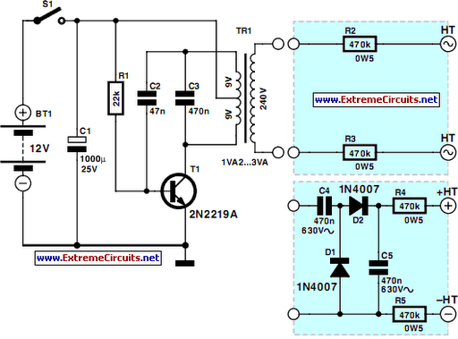
Power line fluctuations and cut-offs can damage electrical appliances connected to the line, particularly domestic appliances such as refrigerators and air conditioners. Operating a refrigerator on low voltage can lead to excessive current flowing through the motor, resulting in...
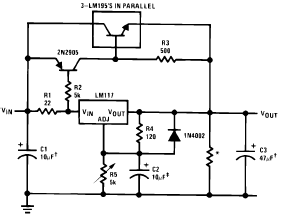
The following circuit diagram illustrates the application of the LM117 as a high current adjustable regulator. The LM117 is capable of supplying more than 1.5A. The LM117 is a popular adjustable voltage regulator that is designed to provide a stable...
As is commonly the case, this supply was born of necessity. There is absolutely nothing special about the circuit, except that as shown, it is quite capable of up to 20 Amps intermittently or 10A continuous. Simply use a...
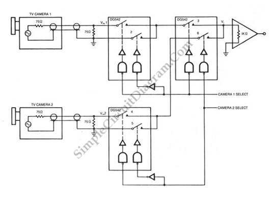
A video switch is necessary to multiplex several video sources, allowing multiple cameras to be displayed sequentially on a single monitor. This multiplexing process... A video switch serves as a critical component in video signal management, particularly in applications where...

This document illustrates the configuration of the high-precision, high-impedance OPA2111 amplifier. The total voltage circuit is designed for a magnification of Av = 10 (1 + 2R2 / R1), achieving a total gain of 1000 times. A gain stage...
This project is designed to prevent unauthorized access to personal belongings left on a beach towel while swimming, and it can also be utilized in office or workshop settings. The circuit is compact and can be powered by simple...
Warning: include(partials/cookie-banner.php): Failed to open stream: Permission denied in /var/www/html/nextgr/view-circuit.php on line 713
Warning: include(): Failed opening 'partials/cookie-banner.php' for inclusion (include_path='.:/usr/share/php') in /var/www/html/nextgr/view-circuit.php on line 713