
High Pass Filter Tutorial
The passive high pass filter circuit is an essential component in electronics, designed to allow signals with a frequency higher than a certain cutoff frequency to pass through while attenuating signals with frequencies lower than the cutoff. This type of filter typically utilizes resistors (R) and capacitors (C) in its construction, forming an RC circuit that defines its frequency response characteristics.
The first-order passive high pass filter consists of a resistor and a capacitor arranged in series, with the output taken across the resistor. The cutoff frequency (fc) is determined by the values of the resistor and capacitor using the formula:
fc = 1 / (2πRC)
In this equation, fc is expressed in hertz (Hz), R in ohms (Ω), and C in farads (F). At frequencies above the cutoff, the output voltage across the resistor increases, while at frequencies below the cutoff, the output voltage decreases significantly.
The Bode plot is a graphical representation of the filter's frequency response, illustrating how the gain and phase shift of the output signal vary with frequency. The gain plot typically shows a slope of +20 dB/decade above the cutoff frequency, while the phase plot indicates a phase shift that approaches +90 degrees as frequency increases.
Construction of a passive high pass filter is straightforward. The components required include a resistor, a capacitor, and a breadboard or PCB for assembly. The resistor and capacitor are connected in series, and the output is taken from the junction between the resistor and the capacitor. Proper consideration should be given to the power ratings and tolerances of the components to ensure reliable performance within the desired frequency range.
In summary, the passive high pass filter is a fundamental circuit utilized in various applications, including audio processing, signal conditioning, and communication systems, where it is necessary to eliminate unwanted low-frequency noise while preserving higher frequency signals.Electronics Tutorial about Passive High Pass Filter Circuit including Passive RC High Pass Filter First Order Frequency Response, Bode Plot and Construction.. 🔗 External reference
Related Circuits
Energia is a rapid prototyping platform for the Texas Instruments MCU Launchpad. It is based on Wiring and Arduino and utilizes the Processing IDE. Energia serves as an accessible development environment for users working with Texas Instruments' microcontroller units (MCUs)...
The automotive electronic code lock circuit is depicted above. IC1 is a dedicated lock for the integrated circuit 5G058, with its designated pins connecting an external key switch to the power supply. There are six valid input keys, and...
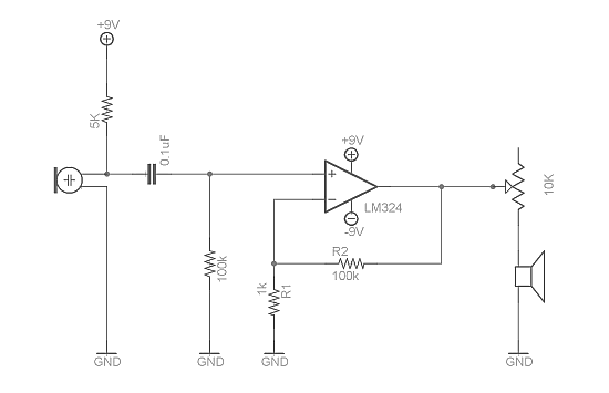
Afroman discusses the fundamentals of utilizing an operational amplifier to amplify small voltage signals and constructs a circuit designed to detect very faint sounds using a microphone. For further details about amplifiers, it is recommended to search for inverting...
It can safely charge a 7-cell RC2000 pack in about 14 minutes, and an RC2400 or CP2400SCR pack in about 17 minutes. As a NiCd cell is being charged, two things happen which affect its temperature. Due to resistive...
These filters are useful for equalisation, analysis and other tasks such as the Sound to Light converter (Project 62) or even a fully functional Vocoder. For those who have not heard of the vocoder, it is a device that...
A bandpass filter allows a specific range of frequencies to pass while rejecting frequencies that fall outside the upper and lower limits of the passband. The frequencies that are permitted to pass are referred to as the passband, which...
Warning: include(partials/cookie-banner.php): Failed to open stream: Permission denied in /var/www/html/nextgr/view-circuit.php on line 713
Warning: include(): Failed opening 'partials/cookie-banner.php' for inclusion (include_path='.:/usr/share/php') in /var/www/html/nextgr/view-circuit.php on line 713