
High Performance Regen Receiver
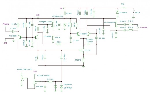
The regenerative receiver kit is designed to provide users with a high-quality radio frequency (RF) reception experience. The core of this receiver is the regenerative detector circuit, which operates by feeding part of the output signal back into the input. This feedback mechanism increases the gain and sensitivity of the receiver, allowing it to pick up weaker signals that might otherwise be lost in noise.
The kit typically includes essential components such as a power supply, tuning capacitors, inductors, resistors, and a circuit board for assembly. Users are required to solder the components onto the board according to the provided schematic diagram, which outlines the connections and placements of each component. The regenerative receiver can be tuned across various frequency bands, making it versatile for different applications, including amateur radio and shortwave listening.
In addition to its sensitivity, the regenerative receiver is known for its simplicity and cost-effectiveness, making it an ideal project for electronics enthusiasts and hobbyists. The design allows for adjustments to be made for optimal performance, including fine-tuning the feedback loop to achieve the desired level of gain without introducing unwanted oscillations.
Overall, the regenerative receiver kit represents an excellent opportunity for learning and experimentation in the field of RF electronics, combining practical assembly skills with the theoretical understanding of radio wave reception.A new high-performance regenerative receiver is available as a kit. Using a new regenerative detector circuit allows a good performance regarding sensitivity.. 🔗 External reference
Related Circuits
This project originates from the past and has demonstrated significant success. It serves as the foundation for an 8-channel proportional R/C (AM) and 145MHz FM chat box. The receiver design is straightforward and includes a single transistor mixer followed...
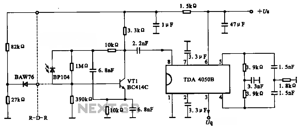
The circuit depicted is an infrared receiver circuit. It primarily consists of an infrared remote control signal switching circuit, designated as VRI, along with signal amplification, filtering, and rectifying integrated circuits, specifically the TDA4050B. The BP104 component serves as...

In this circuit, a Burr-Brown operational amplifier provides a slew rate of 135 V/μs. The inclusion of capacitor C2 reduces the high-frequency feedback factor to less than unity, enabling higher slew-rate amplifiers to be compensated for gains greater than...
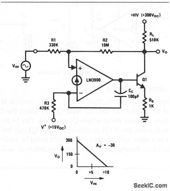
This circuit is an inverting amplifier with an output voltage swing from approximately 0 to +300 V. Any transistor can be utilized for Q1, as long as the breakdown voltage exceeds 300 V (since the full high voltage will...
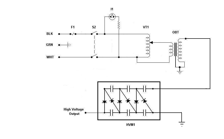
Using components from old microwave ovens, TV sets, and oil burners, it is possible to construct an economical instrument capable of producing high voltage outputs. The primary element in this setup is a voltage multiplier, which should be assembled...
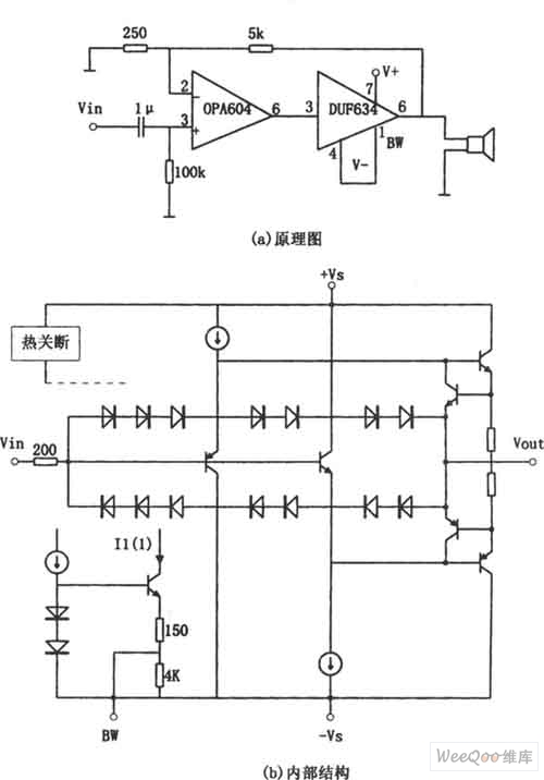
The provided image depicts a high-performance and low-power audio power amplifier circuit. The initial stage utilizes the MOSFET hi-fi operational amplifier OPA604, while the subsequent stage employs the high-speed buffer BUF634. Voltage series negative feedback is implemented between the...
Warning: include(partials/cookie-banner.php): Failed to open stream: Permission denied in /var/www/html/nextgr/view-circuit.php on line 713
Warning: include(): Failed opening 'partials/cookie-banner.php' for inclusion (include_path='.:/usr/share/php') in /var/www/html/nextgr/view-circuit.php on line 713