
High Power IR Infrared Transmitter
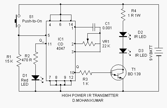
The infrared transmitter circuit is designed for remote activation of devices using infrared light signals. It typically consists of a microcontroller or a signal generator that modulates the output signal to control the infrared LEDs. The modulation can be achieved through various techniques, such as pulse-width modulation (PWM), which allows for efficient power management and signal integrity over longer distances.
The circuit may include a power supply section that provides the necessary voltage and current to the IR LEDs. The choice of infrared LEDs is crucial, as their wavelength and output power determine the effective range and performance of the transmitter. Commonly used wavelengths for IR communication are around 850 nm to 940 nm, which are well-suited for most IR receivers.
To ensure reliable operation at distances exceeding 10 meters, the circuit should incorporate appropriate lensing or focusing elements that help direct the emitted infrared light toward the intended receiver. Additionally, the use of a suitable housing can protect the components from environmental factors while maintaining the integrity of the emitted signal.
The output stage of the transmitter circuit typically includes a driver circuit capable of supplying the required current to the infrared LEDs. This may involve the use of transistors or MOSFETs to switch the LEDs on and off rapidly, allowing for effective communication with the IR receiver.
Overall, this infrared transmitter is an essential component in various applications, including remote control systems, wireless data transmission, and automation solutions, where non-line-of-sight operation is required.This Infrared transmitter can activate IR based switching circuits from a distance of 10 meters or more. It is a high power IR transmitter driving two IR L.. 🔗 External reference
Related Circuits
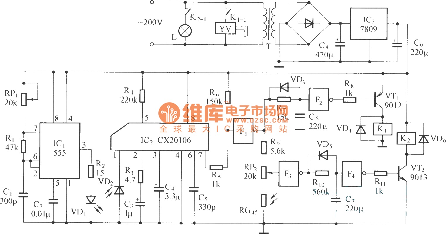
The circuit consists of the following components: (1) An infrared emitter which utilizes a multi-harmonic oscillator based on a 555 timer circuit. The oscillation frequency is determined by the values of RP1, R1, and C1, resulting in a frequency...

This design outlines a tracking transmitter for audio tones operating in the FM band frequency. The circuit can function as either a signal transmitter or a remote control transmitter and utilizes only readily available components. It has a transmission...
Its frequency depends on the capacitance of the vary cap diode. The center frequency is changed by varying the biasing voltage of the vary cap through the 47K pot. You can use a 75cm telescopic antenna or simply a...
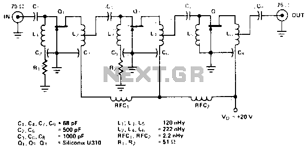
The amplifier circuit is designed for a center frequency of 225 MHz, with a bandwidth of 50 MHz at 1 dB, low input voltage standing wave ratio (VSWR) in a 75-ohm system, and a gain of 24 dB. Three...
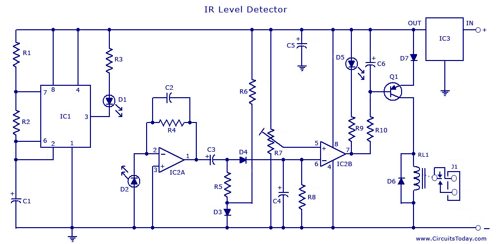
An infrared (IR) sensor or detector circuit diagram utilizing a 555 integrated circuit (IC), primarily employed as a water level or liquid level sensor and proximity detector circuit. The described circuit employs a 555 timer IC configured in a monostable...
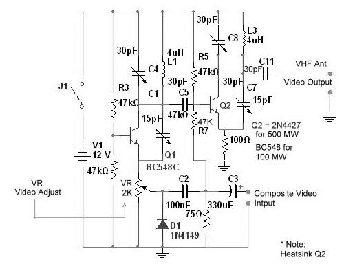
Tuned circuits consist of C4, L1, C8, L3, and two 15 pF trimmer capacitors positioned across the collectors and emitters of both transistors. Other NPN transistors such as BC54, 2N3642, and 2N3643 may also be suitable. The circuit is...
Warning: include(partials/cookie-banner.php): Failed to open stream: Permission denied in /var/www/html/nextgr/view-circuit.php on line 713
Warning: include(): Failed opening 'partials/cookie-banner.php' for inclusion (include_path='.:/usr/share/php') in /var/www/html/nextgr/view-circuit.php on line 713