
High power siren circuit using CD40106
This siren circuit operates on a principle of frequency modulation to create a loud and attention-grabbing sound, which is particularly useful in alarm systems. The CD4046 IC serves as the heart of the circuit, functioning as a phase-locked loop (PLL) that generates a stable frequency output that can be varied by changing the values of the resistors and capacitors in the circuit. The choice of using four transistors allows for effective current amplification, ensuring that the output to the horn speaker is powerful enough to be heard over significant distances or in noisy environments.
The design's compact nature makes it suitable for applications where space is at a premium, while still offering robust performance. The use of a PCB with only two layers simplifies the manufacturing process and reduces costs. Proper soldering techniques are emphasized to prevent failure, especially with sensitive components like ICs and polarized capacitors, which must be oriented correctly to function properly.
In addition to its application in theft protection systems, this siren circuit can be adapted for various other uses, such as emergency alerts or signaling devices in industrial settings. The flexibility in the design allows for modifications to be made, such as changing the frequency of the output sound or integrating additional features like remote activation or deactivation.
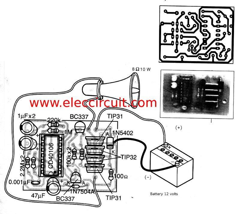
Overall, this siren sound generator circuit exemplifies an effective solution for creating a loud alarm signal, leveraging basic electronic components to achieve a significant auditory output, with potential applications in security and emergency response systems.This is a simple siren sound that high power output and very noisy. ICs, Digital ICs are easy to use number CD4046 Inverter circuit and four transistor power increase current out to horn speaker 20 watt 4ohm 8ohm. Operation of the circuit when the circuit is connected to power. Frequency generator circuit starts, the cycle will be the second fr equency generator set to a first set of IC1 / 1, R2, C2 generator frequency 1Hz. Output can be modulated. With integrated suite 2, which is R3, R4, C3, ZD1 the modulation and frequency of Set 2 is the origin of IC1 / 2, R5, C4 are the output out of pin 12 of IC1 / 2 to Pin 1 of IC1 / 3. The output from the pin 2 is connected to IC1 / 4, IC1 / 5 and pin B of the Q1 output of IC1 / 4, IC1 / 5 is connected to pin B of Q2.
we can observe that Q1 and Q2 will run switch. Well, if work makes Q1 Q4, Q5 run a current through the speakers and will work if Q2 Q3, Q6 running a current flowing through the speakers. The nature of the circuit of Q3-Q6 will result in high currents flowing through the speakers, the sound of the siren is very loud.
As said at the beginning of the subject that. The PCB of the project have very small size just two stamps only. If not believe, then take a look at Figure 2. Really high efficient. Who wants to be redesigned to be smaller. Device should be soldered onto the PCB carefully, especially IC, transistors. And equipment such as polar Electrolytic capacitors, must be correct. Certifies that, this circuit of course works. This is a super siren is small. It can be applied compatible with various theft protection circuit, decidedly For example, to prevent a home burglary, car theft protection, or want to use a different alarm sirens. This be Emergency power siren Circuit 6 watt sizes. It use Digital IC number IC 4011 perform produce the frequency pulse generator, be beep danger character.
And have power mosfet wasp use a loudspeaker 8 ohm sizes and are large-sized loudspeaker. for have a voice as the last. For power supply Source use 12 Volt sizes that have can give current get tall about 1 Amp a little like and Power Mosfet should hold let off the heat with. The detail is other, friends, see in the circuit has yes. 🔗 External reference
Related Circuits

Primarily utilized for single-shot timing, shaping, and delay applications. This is achieved through a monostable trigger circuit using the 555 integrated circuit. The 555 timer IC is a versatile component widely employed in various electronic applications, particularly in generating precise...
The circuit does not fail under slight variations, even if the input/output electric current characteristics are exceeded. Failure occurs only during a short circuit or extreme conditions at the output. The operation of the circuit is explained as follows:...
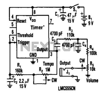
This metronome operates on a current of only 0.25 mA, making it suitable for battery-powered applications. It offers a tempo range from 34 to 246 beats per minute. The circuit can utilize a CMOS timer, such as the LM555...
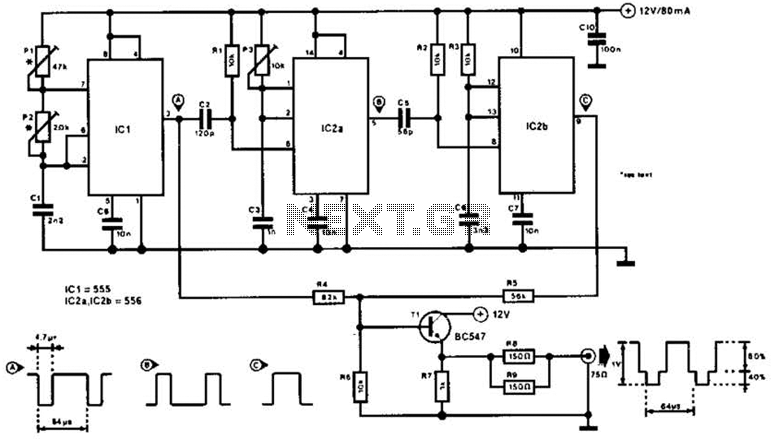
The video master comprises a series of converters that allocate all video sources to unused UHF channels. These channels are then combined with standard TV channels, whether terrestrial or cable, into a single cable. This single cable can subsequently...
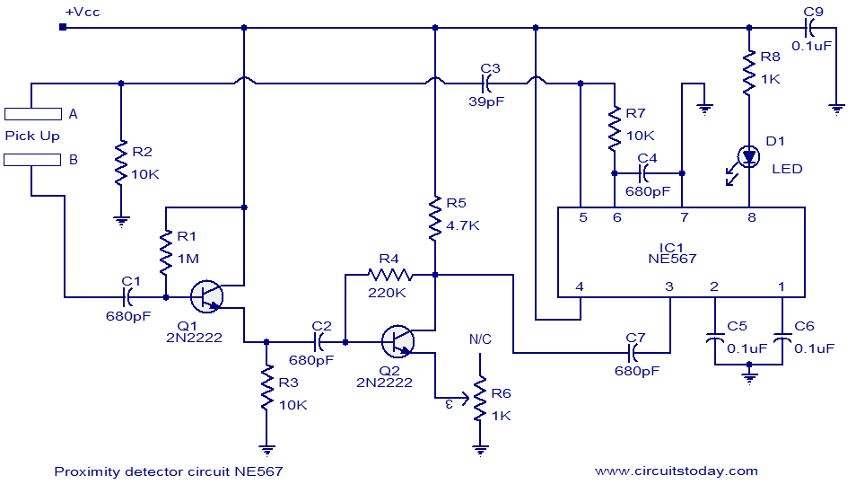
A simple proximity detector circuit utilizing the NE567 integrated circuit (IC). The circuit activates an LED when an object approaches the sensor. The NE567 is a versatile phase-locked loop (PLL) device commonly used for applications such as proximity detection due...
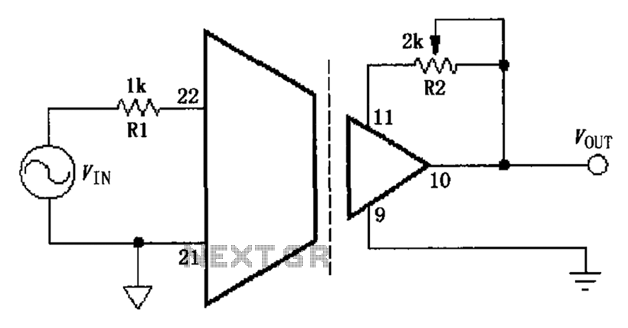
The gain adjustment circuit for the ISO103 is illustrated. The circuit features a gain trimming potentiometer, R2, which serves to enhance the gain accuracy and offset of the ISO103, thereby allowing for external adjustments. R2 provides a gain trim...