
High-pressure direct current power supply scheme of the new low ripple
The voltage tracking circuit is essential for ensuring the normal operation of the device, particularly due to the need for voltage equilibrium when connecting power in parallel. The two-way voltage amplitudes must remain constant. To achieve this, the device parameters must be identical, and an automatic regulation circuit is required for comparison and output voltage matching. The design of the working phase of the circuit is described, including an isolating circuit that effectively mitigates system noise and ground loop interference. The detected output voltage is discretized to prevent instability when compared directly by operational amplifiers, and the response rate of the comparator circuit can be conveniently adjusted. This modulation is achieved through the isolated output voltage using a sawtooth wave, transforming the detected voltage signal into a square wave signal that maintains a direct proportionality to pulse width and voltage. A well-designed RC smoothing circuit is necessary based on the frequency domain for output and input filtering.
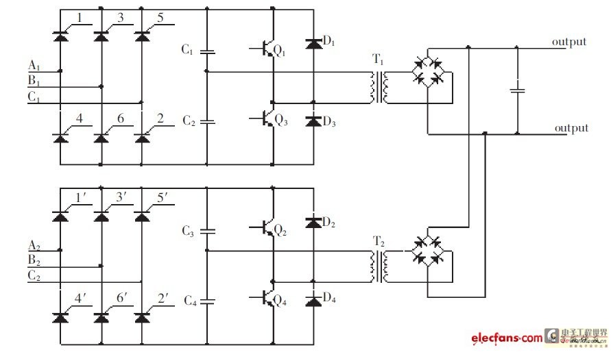
For ease of debugging, the prototype uses a triode thyristor for commutation, specifically the KK200 model produced by the Xi'an Electric Technology Research Institute. The three-phase system passes through a step-down transformer with a transformation ratio of 10:1 to supply two rectifier bridges. The three-phase fully-controlled rectifier bridge generates a direct current average voltage calculated as Ud = 1.35U1cos(θ), where U1 is the mean value of the three-phase line voltage. Given that the mean line voltage entering the rectifier bridge is 380 V, the fully-controlled three-phase bridge commutates to deliver a maximum direct current average voltage of 51.3 V, derived from the equation 380*1.35/10. The transformer ratios for T1 and T2 are set at 1:40.
In summary, this high-pressure direct current power supply system leverages advanced inverter technology and rectification methods to produce stable, low ripple direct current, ensuring efficient power management and voltage regulation through careful circuit design and component selection. The system's robustness is further enhanced by its ability to maintain voltage equilibrium and reduce ripple through strategic capacitance management.The high-pressure direct current power supply has been already increasingly extensive. The method that this literary grace outputs in parallel with the power of double-channel gets the direct current of the low ripple. Today when the gas switching tube frequency is limited, this method can receive the direct current of the low ripple in lower in frequency cases.
The main circuit contains two suits of inverter circuit of totally identical semi-bridge, reverse the on-off element and choose every IGBT. and adopt the independent three-phase fully-controlled rectifier bridge to supply power all the way, the inverter circuit adopts PWM way, operating frequency is far higher than resonant frequency, goes against and changes back voltage waveform into the rectangular wave. The power regulation of the circuit is realized by controlling moving the phase angle of the full-controlled rectifier bridge.
The trigger impulse parameter of IGBT: 0 kHz is 45% of 20 kHz, duty ratio, -5 V 15 V, the pulse phase difference of upper and lower bridge arms is shown as in Fig. 3 in half a cycle, the output waveforms of two roads and half bridges of inverter circuit are shown as in Fig.
4. Connect the two-way voltage in parallel, can get the straight voltage. It is obvious, reduce the ripple while strengthening and outputting capacitance value and or adopt a plurality of electric capacity parallel ways to reduce ESR value. Tracking circuit of voltage 2 Because of adopting two-wayly to export to obtain straight direct-current volts in parallel, the key issue of normal operation of the apparatus is a two-way voltage equilibrium problem of connecting the power in parallel, namely require the two-way voltage amplitude that outputs to keep the same constantly.
For make two-way to output, keep unanimity, yuans of device parameter should choose unanimity, need one the intersection of output voltage and finding, compare and the automatic regulation circuit, the circuit working phase designed actually is shown as in Fig. 5. Mainly include isolating and part of a circuit of discretization two in the detection circuit, the isolating circuit can inhibit the system noise effectively, dispel the interference of the ground loop.
Discretize the detected output voltage in order to solve the problem that when close analog quantity is compared directly operational amplifier is outputted to shake, at the same time can make postern response rate conveniently regulable of comparator circuit. It is realized that modulated through the isolated output voltage by the sawtooth wave specifically in the circuit of discretization.
It turns the detected voltage signal into the square wave signal that pulse width and its voltage are directly proportional to. In particular application, should design the reasonable RC smoothing circuit according to frequency domain.
Output and its inputting of the electric-wave filter to For: For convenience debug, the prototype machine adopts the triode thyristor to commutate, this prototype machine chooses KK200 that the electric electron technology research institute of Xi`an produces and commutates the triode thyristor. Three-phase electric passes a step-down transformer transformation ratio 10: 1Receive 2 rectifier bridges.
The three-phase fully-controlled rectifier bridge outputs the direct-flow average voltage: Ud =In the 1. 35U1cos type, U1 input the mean value of the three-phase line voltage; three-phase bridge is full-controlled to commutate the control angle.
The mean value of the line voltage of incoming line of rectifier bridge of this prototype machine is 380 V, adopt three-phase bridge to be full-controlled and commutate, so the rectifier bridge outputs the direct-flow average voltage of maximum 380*1. 35 / 10=51. 3 V Left and right sides. Transformation ratio 1:40 of T1, T2 voltage transforme 🔗 External reference
Related Circuits
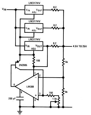
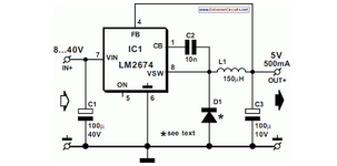
The LM317HV adjustable regulator is capable of supplying over 1.5A across an output voltage range of 1.2V to 57V. The design of this high current power supply is straightforward, as the LM317HV requires only a few external resistors to...
This current-limiting circuit, illustrated as part of a small bench power supply, can be utilized with any dual-rail current source. The section of the circuit on the left limits the current entering the dual voltage regulator (IC4 to IC7)...
A 1997 Ford Thunderbird experienced a failure of the blower/fan when the air conditioning was activated, accompanied by a snapping sound under the instrument panel. This resulted in no airflow for the air conditioning, heater, or defrost functions. The...
National Semiconductor has been producing and designing integrated circuits (ICs) for use in switch-mode power supplies for many years. The application of these devices is standard. National Semiconductor has established a significant presence in the design and manufacturing of integrated...
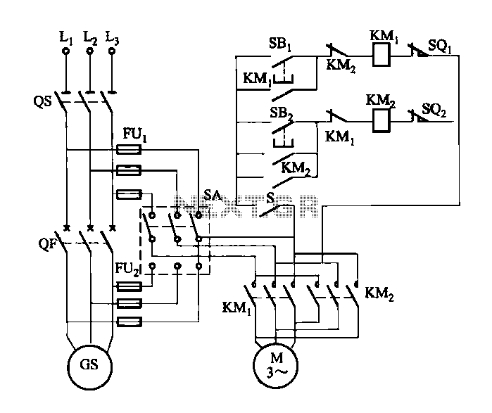
FIG M is a variable speed motor control for the opening and closing of a wicket gate. It features an electric governor. The system is activated by a power switch (SA) located on the front grid, and a toggle...
This article provides a comprehensive overview of the methodology used for testing power supplies (PSUs) in three main sections. The first section outlines the PSU parameters that are evaluated and specifies the testing conditions. The second section defines commonly...
Warning: include(partials/cookie-banner.php): Failed to open stream: Permission denied in /var/www/html/nextgr/view-circuit.php on line 713
Warning: include(): Failed opening 'partials/cookie-banner.php' for inclusion (include_path='.:/usr/share/php') in /var/www/html/nextgr/view-circuit.php on line 713