
High-q-notch-filter
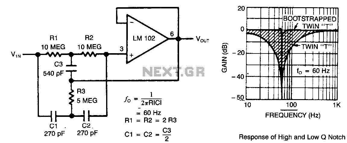
This circuit illustrates a twin-T network connected to an LM102 to form a high-Q, 60-Hz notch filter. The junction of R3 and C3, which is typically grounded, is bootstrapped to the output of the follower. Due to the low output impedance of the follower, neither the depth nor the frequency of the notch is altered; however, the Q factor increases in proportion to the amount of signal fed back to R3 and C3. The response of a standard twin-T is shown alongside the response with the follower integrated.
The described circuit utilizes a twin-T notch filter configuration, which is known for its ability to attenuate a specific frequency while allowing other frequencies to pass with minimal loss. The twin-T network is composed of resistors and capacitors arranged in such a way that it creates two paths for the signal: one through the resistors and the other through the capacitors. This configuration allows for precise tuning of the notch frequency, which in this case is set to 60 Hz.
In this particular design, the LM102 operational amplifier is employed as a voltage follower. The output of the follower is connected to the junction of resistors R3 and capacitor C3, which is typically grounded in standard configurations. By bootstrapping this junction to the output of the follower, the circuit takes advantage of the low output impedance provided by the operational amplifier. This low impedance ensures that the characteristics of the notch filter, specifically its depth and frequency, remain stable and unaffected by loading conditions.
The enhancement of the Q factor, or quality factor, is a significant feature of this design. The Q factor describes the selectivity of the filter; a higher Q indicates a sharper notch, which means that the filter is more effective at rejecting the target frequency while allowing adjacent frequencies to pass. In this circuit, the Q factor is increased based on the feedback signal applied to R3 and C3. The feedback effectively modifies the gain of the filter, allowing for greater control over the notch's sharpness.
The accompanying response curves illustrate the performance of the twin-T network both in its standard form and with the voltage follower included. The addition of the follower not only stabilizes the notch characteristics but also improves the overall performance of the filter, making it a valuable solution for applications requiring precise frequency attenuation, such as audio processing, signal conditioning, or noise reduction in various electronic systems.This circuit shows a twin-T network connected to an LMl02 to fonn a high-Q, 60-Hz notch filter. The junction of R3 and C3 which is normally connected to ground, is bootstrapped to the output of the follower. Because the output of the follower is a very low impedance, neither the depth nor the frequency of the notch change;
however, the Q is raised in proportion to the amount of signal fed back to R3 and C3. Shown is the response of a normal twin-T and the response with the follower added. 🔗 External reference
Warning: include(partials/cookie-banner.php): Failed to open stream: Permission denied in /var/www/html/nextgr/view-circuit.php on line 713
Warning: include(): Failed opening 'partials/cookie-banner.php' for inclusion (include_path='.:/usr/share/php') in /var/www/html/nextgr/view-circuit.php on line 713