
High sensitivity alarm

The high-sensitivity alarm circuit is designed to detect changes in ambient light levels, utilizing a light-dependent resistor (LDR) as the primary sensing element. The LDR's resistance decreases with increasing light intensity, allowing the circuit to respond to varying light conditions effectively. The three resistors in the circuit are configured to create a voltage divider, which helps establish the reference voltage levels required for the comparator operation.
The self-excited oscillator generates a square wave signal, which is instrumental in driving the dual-contact switches. This switching action allows the capacitors to charge and discharge at a controlled rate, ensuring that the circuit can sample the voltage levels accurately. The operational amplifier configured as a comparator plays a critical role in determining when the circuit should trigger an alarm. By comparing the voltages at its inverting and non-inverting inputs, the comparator can detect significant changes in light levels.
The sample-and-hold functionality of the circuit allows it to maintain the last sampled voltage during periods of low light fluctuation, ensuring that the alarm remains stable and responsive only to significant changes in light conditions. The monostable multivibrator, triggered by the comparator's output, generates a single pulse of a specified duration, which can be used to activate the relay. The relay serves as the output mechanism to sound an alarm or activate other devices in response to the detected light changes.
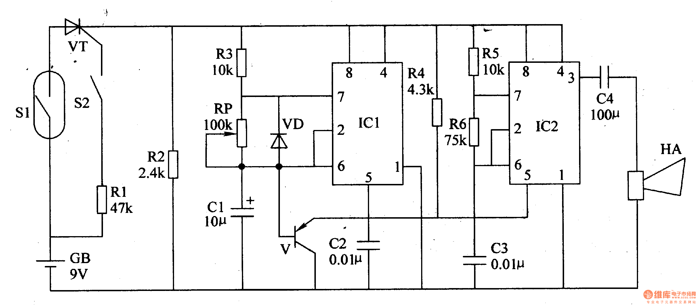
Overall, this circuit design is effective for applications requiring high sensitivity to light changes, such as security systems, automatic lighting controls, or environmental monitoring systems. The careful selection of components and their configuration ensures reliable performance and responsiveness to light variations. As shown in the simplified block diagram of the high sensitivity of the alarm circuit, wherein the photoresistor LDR and three ordinary resistor connected. Thus, when the light is at full dark to light changes between full from the potential diagram X point range of about 1/4 to 3/4 of the supply voltage. This potential is applied to the input terminal while the two dual-contact switches. A self-excited oscillator and an inverter circuit controls a combination of these two switches alternately switching, typically a few Hz switching frequency, so that the two capacitors are alternately charged.
As the double-contact switch in the off state its resistance is large, and the comparator constituted by the operational amplifier input impedance is also high. And the capacitor charge storage capacitor between the double contact switch and the comparator plates.
Therefore, when the transfer switch, the discharge rarely. This constitutes a sample and hold circuit. When the charge (potential) capacitor comparator inverting input terminal (-) when the potential rises above the inverting input terminal (+) potential, or when non-inverting input terminal potential lower than the potential of the inverting input terminal, the comparator output becomes low, using the low to trigger followed by a single stable and relay.
Related Circuits

The circuit utilizes a 555 integrated circuit (IC) functioning as an astable multivibrator. When a positive 9 volts is applied to pin 8, the circuit generates sound through a speaker. The connection to pin 8 is routed through a...
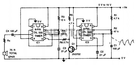
This circuit simulates the sound of an American police siren. IC2 is configured as a low-frequency astable multivibrator, producing a cycling period of approximately 6 seconds. The slowly varying ramp waveform generated on capacitor C1 is fed to the...

This circuit is not easy to build, but it provides excellent audio quality. It serves as a high-quality preamplifier, capable of driving high-quality power amplifiers while delivering good sound. The described circuit functions as a high-fidelity audio preamplifier, designed to...
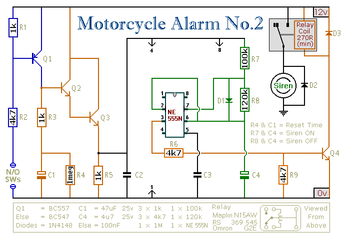
This circuit features an intermittent siren output and automatic reset. It can be operated manually using a key switch or a hidden switch, and it can also be wired to activate automatically when the ignition is turned off. By...
The simple pressure sensor alarm is constructed using a few inexpensive and readily available components. The operation of this circuit is straightforward and self-explanatory. When powered by a 9V compact battery, the active piezo sounder at the output of...
This article introduces a motorcycle anti-theft alarm that utilizes the 555 timer integrated circuit. The alarm is activated when a thief attempts to move the motorcycle vertically. The circuit consists of a trigger circuit and an alarm circuit, as...