
High Voltage Converter: 90V From 1.5V
The described circuit utilizes the LT1073 switching regulator, which is a highly efficient device for stepping up low input voltages to higher levels. In this configuration, the input voltage of 1.5V is boosted to 90V, making it suitable for applications requiring high voltage from low power sources. The operation of the circuit is centered around the switching transistor that engages in rapid on-off cycles, allowing for the energy storage in the choke (inductor) L1.
When the transistor is activated, it connects L1 to ground, allowing current to flow through it and creating a magnetic field. The energy stored in this magnetic field is released when the transistor turns off, inducing a voltage spike that forward-biases diode D1. This spike charges capacitor C3, which serves as an energy reservoir.
The cascading arrangement of diodes (D1, D2, D3) and capacitors (C2, C3, C4) forms a voltage multiplier. Each diode conducts during the charging cycle, and the capacitors store charge, effectively increasing the voltage output. The design ensures that the output voltage is quadrupled due to the series and parallel arrangement of these components.
The resistors forming the potential divider play a critical role in regulating the output voltage by providing feedback to the control loop of the LT1073. The selection of high-precision, low-tolerance metal film resistors is vital for maintaining stable operation and ensuring that the output voltage remains at 90V under varying load conditions.
The use of fast recovery diodes, such as the MUR120, is essential to handle the high reverse voltages without significant losses, thereby improving the efficiency of the circuit. The choke selected, Coilcraft DO1608C-154, is designed to handle the required current and voltage levels, ensuring reliable performance.
Overall, this circuit design is effective for applications requiring a compact solution for generating high voltages from low power sources, capable of delivering several milliamps of current for various electronic applications.The circuit shows one way of obtaining a voltage of 90V from a 1. 5V battery supply. The LT1073 switching regulator from Linear Technology ( operates in boost mode and can work with an input voltage as low as 1. 0 V. The switching transistor, which is hidden behind connections SW1 and SW2, briefly takes one end of choke L1 to ground.
A magnetic fiel d builds up in the choke, which collapses when the transistor stops conducting: this produces a current in diode D1 which charges C3. The diode cascade comprising D1, D2, D3, C2, C3 and C4 multiplies the output voltage of the regulator by four, the pumping of C2 causing the voltage developed across C4 via C3, D2 and D3 to rise.
Finally, the regulator control loop is closed via the potential divider (10 M and 24 k). These resistors should be 1 % tolerance metal film types. With the given component values, fast diodes with a reverse voltage of 200 V (for example type MUR120 from On Semiconductor and a choke such as the Coilcraft DO1608C-154 ( an output voltage of 90 V will be obtained. The output of the circuit can deliver a few milliamps of current. 🔗 External reference
Related Circuits
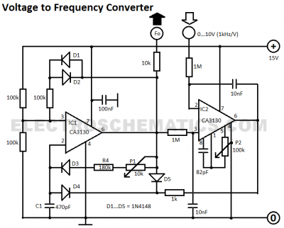
This voltage-to-frequency converter circuit features a voltage-controlled oscillator with a small deviation of 0.5%. The integrated circuit IC1 operates as a multivibrator. The voltage-to-frequency converter circuit is designed to convert an input voltage into a corresponding frequency output. The core...
Many modern audio recorders are now compatible with digital input S/PDIF (Sony/Philips Digital Interface). Devices like CD changers, MiniDisc recorders, computer sound cards, and the like work with digital signals using the S/PDIF protocol. This digital connection between two...
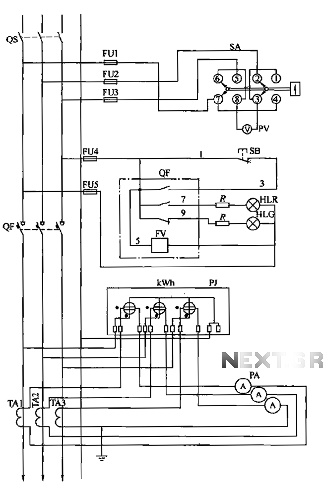
The BSL is illustrated in a low-voltage distribution panel wiring diagram. It consists of three main components: the voltage measuring circuit, secondary circuit protection, and the energy metering circuit. (1) The voltage measuring circuit includes a voltage switch (SA)...
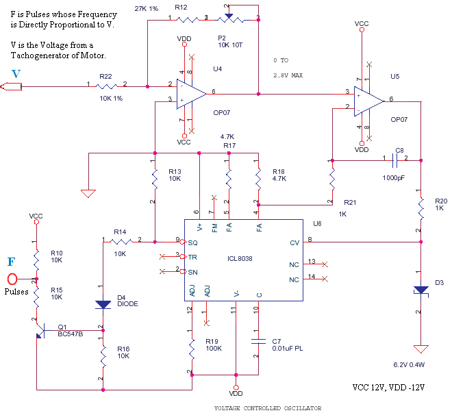
This is a small circuit designed to drive an impact counter, with the central component being the ICL8038. The circuit is intended for use with a motor that drives a conveyor, which includes a feedback mechanism known as a...
Since my page was first posted, I have received a number of emails asking about a high current power supply. I looked around, but couldn’t find one that was suitable. So, I designed this. It is a linear supply,...
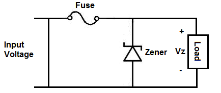
An overvoltage protection circuit is designed to safeguard electronic components from excessive voltage that could potentially cause damage or destruction. This project involves constructing a straightforward yet effective overvoltage protection circuit using a fuse and a zener diode as...
Warning: include(partials/cookie-banner.php): Failed to open stream: Permission denied in /var/www/html/nextgr/view-circuit.php on line 713
Warning: include(): Failed opening 'partials/cookie-banner.php' for inclusion (include_path='.:/usr/share/php') in /var/www/html/nextgr/view-circuit.php on line 713