
High Voltage Electrolytic Capacitor Reformer
The unit is also very useful in the early stages of testing and repairing valve equipment. This use is detailed elsewhere on this web site, and will not be repeated here. This unit is designed for operation from a mains supply of 220-240V 50/60Hz. The design is not suitable for operation from a 110-120V supply (as used in the USA and some other countries). However suggestions from a visitor to this page, for producing a 120V version, is given at the end of the article.
This unit is connected directly to the mains and produces potentially lethal voltages. Do not allow this unit to be used by young children or persons who are not aware of the dangers. The unit must be prominently labelled with appropriate warnings. It is recommended that this unit is not permanently fitted with a mains plug, so that it cannot be inadvertently connected to the mains. The unit is intended to be used in a workshop situation, by someone who knows what he or she is doing.
Anyone who is familiar with working on valve equipment should be used to dealing with high voltages and therefore able to treat this unit with due respect. This project is definitely not suitable for beginners. The mains supply voltage (220-240V AC) is half wave rectified by D1 and smoothed by C1. R1 is a surge-limiting component, intended to limit the initial inrush current to C1. R1 must be a wirewound component. R2 will gradually discharge C1 and any capacitors that are connected to the output of the unit when the mains supply is switched off.
This will take about 15 seconds with C1 alone, and much longer with additional capacitors connected. The voltage is then regulated by D2, D3 and D4. Note that D4 is short-circuited by SW1 on the 240V setting. R3 is the current limiting component, and will run warm. The zener diodes are rated at 5W. R4 is added in the negative output rail to allow the output current to be monitored without breaking the circuit. This allows a meter to be connected periodically to monitor the current, rather than committing a meter for the whole reforming process.
A voltmeter connected across this resistor will indicate 0 - 3. 5V for 0 - 35mA output current. Thus, the voltage reading should be multiplied by ten to obtain the current in milliamps. R4 could be replaced with a suitable DC milliammeter fitted to the case. R3 will limit the current through the capacitor to a safe limit. If the capacitor leakage current is high, the output voltage will be low due to the voltage drop in R3. The zener diode chain prevents the voltage rising above the rated capacitor voltage when the leakage is lower.
The circuit is constructed on plain matrix board. Do not use Veroboard, as the spacing between the tracks is insufficient for the high voltages involved. A printed circuit board could be designed, but it is not really necessary for a simple design like this.
A suggested circuit board layout is shown, although this may be varied to suit the components and case used. Do not pack the components too close together. R3 will get warm, and should be mounted a little above the surf 🔗 External reference
Related Circuits

U1 is a frequency-to-voltage converter that feeds a sample-and-hold circuit utilizing an LF381 operational amplifier. An LF351 provides a 10-V maximum scale output. The circuit generates a 1-V output per kHz frequency. The described circuit employs a frequency-to-voltage conversion technique,...

This high-voltage white LED driver electronic circuit schematic utilizes the NCP5021 integrated circuit from On Semiconductor. The NCP5021 is designed with an ambient light sensing feature and can drive up to eight LEDs in series for portable backlight applications....
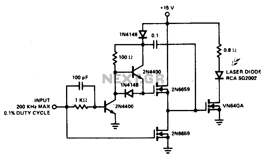
A faster driver can supply higher peak gate current to switch the VN64GA very quickly. The circuit uses a VMOS totem pole stage to drive the high power switch. The described circuit employs a high-speed driver to enhance the switching...
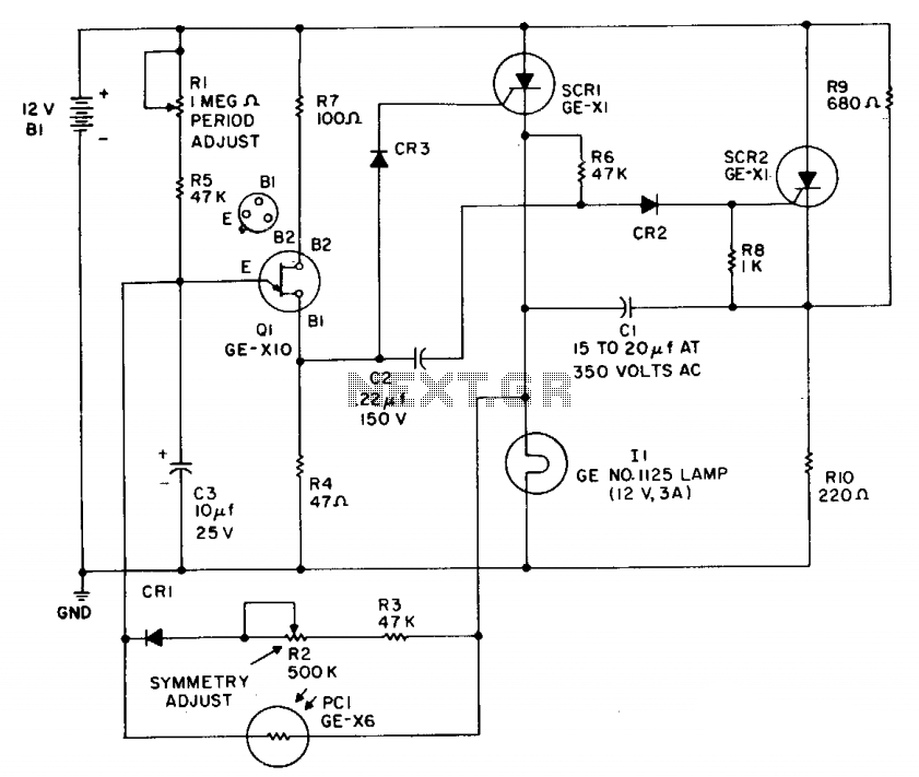
This flasher operates from a 12-volt car or boat battery. It provides an output of 36 to 40 watts, with a variable flash rate of up to 60 flashes per minute. The device features independent control of both on...
The detector is designed to sense and signal to another circuit when an appliance is connected to the mains voltage. An optocoupler, identified as IC1 in the circuit, is utilized for this purpose. The light-emitting diode within the optocoupler...

The inverting input is maintained at a low level via a 10K resistor when the circuit is powered on but not in use. During measurement activities, including calibration measurements where the input is floating, this resistor is disconnected. The...
Warning: include(partials/cookie-banner.php): Failed to open stream: Permission denied in /var/www/html/nextgr/view-circuit.php on line 713
Warning: include(): Failed opening 'partials/cookie-banner.php' for inclusion (include_path='.:/usr/share/php') in /var/www/html/nextgr/view-circuit.php on line 713