
high-voltage-inverter-circuit-diagram.html
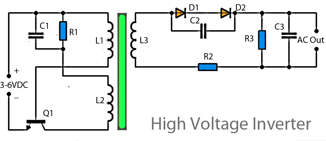
This inverter circuit operates using a transistor and transformer, along with other components, to elevate the voltage. The input supply voltage ranges from 3V to 6V DC, which is then converted to a high voltage AC output. However, the output current is quite low, likely under 0.1A or even less. This inverter is suitable for powering a fluorescent lamp with a maximum power of 10W, but it may take some time to turn on the fluorescent lamps.
The inverter circuit described employs a basic configuration consisting of a transistor, a transformer, and several passive components to facilitate the conversion of low-voltage DC to high-voltage AC. The input voltage range of 3V to 6V DC indicates that this inverter can be powered by common battery sources, making it suitable for portable applications.
The transistor serves as a switch, controlling the flow of current through the primary winding of the transformer. When the transistor is turned on, current flows through the primary winding, creating a magnetic field in the transformer. As the transistor switches off, the magnetic field collapses, inducing a high voltage in the secondary winding of the transformer, which is then output as AC voltage.
The transformer is crucial in stepping up the voltage to the desired level. The turns ratio of the transformer determines the increase in voltage; for instance, a transformer with a turns ratio of 10:1 would increase the input voltage by a factor of ten. However, care must be taken to ensure that the transformer is rated to handle the expected output voltage and power levels.
The low output current, typically under 0.1A, limits the inverter's application primarily to low-power devices, such as a 10W fluorescent lamp. The design may include additional components like capacitors for filtering and resistors for biasing the transistor, ensuring stable operation and minimizing noise.
It is important to note that the inverter circuit may have a delayed response when powering fluorescent lamps. This delay occurs due to the time required for the lamp to ionize and start emitting light, which can be a consideration in applications where immediate illumination is required.
In summary, this inverter circuit is a simple yet effective solution for converting low-voltage DC to high-voltage AC, suitable for low-power applications such as fluorescent lighting, while being mindful of its limitations in output current and response time.This inverter circuit works with a transistor and transformer and other components to increase the voltage becomes high. Input supply voltage ranging from 3V to 6V DC, later it was raised to high voltage AC. However, in this inverter circuit output current is very small, probably under 0. 1A even smaller. However, its use you can apply it on a fluo rescent lamp 10W maximum power only, and that too takes time to switch on fluorescent lamps. 🔗 External reference