
Higher Order Filters
The design of filters is critical in electronic circuits, particularly for applications requiring specific frequency responses. Filters can be categorized into low-pass, high-pass, band-pass, and band-stop types, each serving unique functions in signal processing. The low-pass filter allows signals below a certain cut-off frequency to pass while attenuating higher frequencies, making it essential in audio applications, power supply circuits, and data communication systems.
In practical implementations, the choice of components such as resistors and capacitors directly influences the filter's performance. The quality of these components, including their tolerances and temperature coefficients, must be considered to ensure reliable operation. Additionally, the layout of the circuit board can affect the filter's characteristics due to parasitic capacitance and inductance, which may distort the intended frequency response.
For a fourth-order Butterworth filter, the cascading of two second-order filters not only enhances the steepness of the roll-off but also improves the overall phase response, which is crucial for applications where phase distortion can lead to signal degradation. The design requires careful calculation of component values to achieve the desired cut-off frequency and gain, often utilizing simulation software to predict performance before physical implementation.
In summary, the design and implementation of higher-order filters necessitate a balance between complexity, size, and performance to meet specific application requirements. The understanding of filter behavior, particularly in the stopband and passband regions, is paramount for engineers working in the field of electronics and signal processing.From the discussion made so far on the filters, it may be concluded that in the stopband the gain of the filter changes at the rate of 20 db/decade for first-order filters and 40 db/decade for second-order filters. This means that as the order of the filter is increased, the actual stopband response of the filter approaches its ideal stopband char
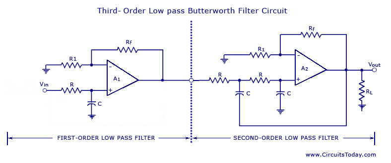
acteristics. In general, a third-order filter produces 60 db/decade, a fourth-order filter produces 80 db/decade and so on. The simplest way to build a third-order low-pass filter is by cascading a first order filter with a second-order.
Similarly a fourth-order low-pass filter can be formed by cascading two second-order low-pass filters. Although there is no limit to the order of the filter that can be formed, as the order of the filter increases, so does its size.
Also the accuracy declines, in that the difference between the actual stopband response and the theoretical stopband re sponse increases with an increase in the order of the filter. The voltage-gain of the first section is optional, it can be set, whatever is required. The voltage-gain of the second section, however affects the flatness of the overall response. If closed-loop gain is kept 1. 586, then the overall gain will be down 6 db (3 db for each section) at the cut-off frequency. By increasing the voltage gain of the second section slightly, cumu lative loss of voltage gain is offset.
By using an advanced mathematical derivation, it can be proved that an Af, of 2 is the critical value required for a maximally flat response. where R and C are the resistance and capacitance of each section. At cut-off frequency, the overall voltage gain is down 3 db. Above the cut-off frequency, the voltage gain drops at a rate of 60 db per decade equivalent to 18 db per octave.
A fourth-order low-pass Butterworth filter is illustrated in figure. It is formed by cascading two second-order low-pass filters. If Af, of 1. 586 is used for both sections, the voltage gain will be down 6 db at the cut-off frequency. By using different gain for each section, we can strike a compromise that produces a maximally flat response. An advanced derivation shows that we need to use Af = 1. 152 for the first section and Af = 2. 235 for the second section. Also, the overall filter gain is equal to the product of the individual voltage gains of the filter sections.
Hence, the overall gain of a fourth-order filter is 1. 152 x 2. 235 = 2. 575. As with the first- and second-order filters, the third- and fourth-order high-pass filters are formed by simply interchanging the positions of the frequency determining resistors and capacitors in the corresponding low-pass filters. The high-order filters can be designed by following the procedures outlined for the first- and second-order filters.
Generally, the minimum-order filter required depends on the application specifications. Although a high-order filter than necessary provides a better stopband response, the high-order filter is more complex, occupies more space and is more expensive. It is worth mentioning here that in all filters, the same resistance and capacitance values are used in the bypass or R-C networks, a definite convenience in selection of components and ease of construction.
This fixes the overall gain of the high-order filters. Furthermore, the 3-db cut-off frequency is always the same and is equal to 1/2 RC 🔗 External reference
Related Circuits

This filter circuit, which utilizes the LM1458 or a similar operational amplifier, has a frequency response ranging from 300 Hz to 3.4 kHz, exhibiting a roll-off of 12 dB per octave outside the passband. Section A serves as the...
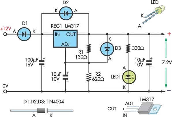
This circuit allows an external 12V SLA battery to power a camcorder that typically uses a built-in 7.2V battery. Obtaining such batteries for older camcorder models can be challenging and costly. The circuit utilizes a standard LM317 adjustable voltage...

Generating sine waves with controlled frequencies over a wide range is challenging when using RC or LC sinusoidal oscillators. However, this can be effectively achieved using a wideband digital square wave oscillator, a counter, and a weighted summing network....
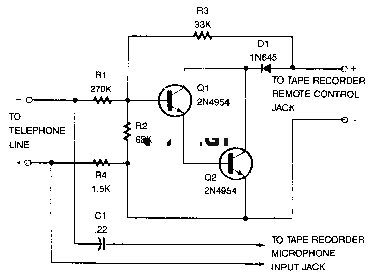
This recorder can be connected to telephone lines almost anywhere, and it does not require an external power source. The switch terminals of the tape recorder are connected to a pair of transistors configured as Darlington pairs, which are...
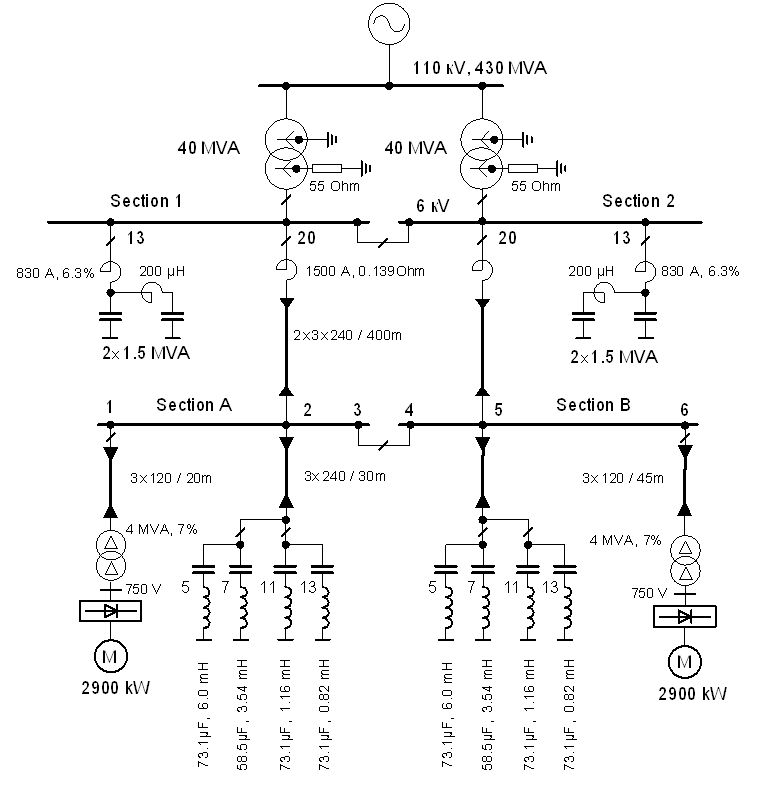
The vertical line indicates the instance of the 5th harmonic filter connection. The diagram illustrates the power system with the designed group of single-tuned filters for a system with a DC drive supplied by a 6-pulse controlled rectifier: PN...
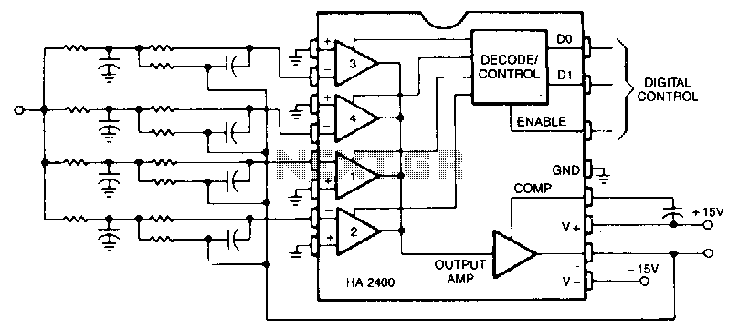
This is a second-order low-pass filter with a programmable cutoff frequency. The circuit should be driven from a low-source impedance, as there are paths from the output to the input through the unselected networks. Virtually any filter function that...