
Highly Efficient 0-100% LED Dimmer
The circuit design employs a straightforward current source configuration, which is crucial for maintaining constant brightness across varying power supply conditions. The core of the circuit consists of two transistors, with the first transistor controlling the base voltage of the second transistor. When the voltage across a 39-ohm resistor exceeds approximately 0.68V, the first transistor reduces the base voltage of the second, effectively regulating the current flowing through the load. This mechanism ensures that the output current remains stable at around 17.5mA, which can be adjusted by changing the resistor value to optimize for different LED specifications.
For instance, substituting the 39-ohm resistor with a 33-ohm resistor will allow for an output current of approximately 20mA, which is critical for ensuring the longevity of high-performance white LEDs. The circuit's design facilitates dimming capabilities by adjusting the base voltage of the controlling transistor, thus modulating the output current supplied to the LEDs. This dimming feature is essential for applications where light levels need to be varied, such as in portable lighting systems or emergency flashlights.
In conclusion, this LED dimmer circuit represents an innovative approach to efficient lighting solutions, emphasizing simplicity and effectiveness in design while offering significant operational advantages in terms of battery life and adaptability to different LED configurations.This webpage describes a highly efficient LED dimmer, or a dimmable LED flashlight, or a switching current source, or whatever you want to call it. Cheap, single-IC, uses commonly available parts, easy to build. Designed to get the longest light out of a (rechargable) battery, ideal in emergency situations: some 24+ hours for a single white LED at
full brightness from a cheap 9V, 200mAh battery. Works well from 4 up to at least 30 Volts; may even vary over time, while the brightness level is maintained essentially constant. Can drive as many LEDs as would normally be possible with the given supply voltage. Efficiency up to 94%(*), or even higher when a cunningly split supply voltage system is used. While I`ve been doing electronics for some 15-20 years, this happens to be my first web-documented project.
That`s because it`s not quite trivial, it wasn`t yet documented anywhere in this form, and it`s potentially useful for more people than only me. Oh, and this project uses ideas from a variety of online sources, so "giving back" is also a motivation.
For this project, some prior experience with electronics is required. I will not answer your questions, sorry. Instead, the explanation below is very detailed indeed. I should probably issue a WARNING for that. On the other hand, if your day job is to design lighting systems for cellphones or the like, this page won`t tell you much you didn`t already know. This project and webpage including all images are copyright © 2006 J. A. Bezemer, and are licensed under the terms of the GNU GPL ‰¥2. This basically means that you`re very free to use and modify and re-publish it, as long as you also publish your source material (e.
g. files from your schematics drawing program), and preferably include a back-reference to this webpage. And if you produce and sell anything based on this project or webpage, you will have to provide all gory details to your customers if they ask for it.
Oh, and before I forget: I cannot be held responsible for anything you do; there is no guarantee that any information on this page is correct (always use independent verification); avoid looking directly into bright LEDs; apply due caution when working with voltages >40V; all trademarks and registered trademarks mentioned on this page are the property of their respective owners. So, that should keep the lawyers happy. (*): "Practically theoretical" value for the special case that the supply voltage is exactly enough to feed the LEDs at full brightness.
The PWM then turns on continuously (100% duty cycle), giving a constant overhead current <1. 2mA; LED current 20mA and only a trifle more loss in R7 and parasitic resistances. Circuit (a) doesn`t need explaining. R depends on the number (and kind) of LEDs and the supply voltage, which isn`t very handy if you want to be independent of either (or both). Oh, and if you don`t know how to calculate R, this project is not for you. To always have the same brightness independent of the number of LEDs and the supply voltage level (think nearly-empty batteries), a current source is a much better solution.
Circuit (b) depicts one variant that I particularly like. I found it on the 4QD-tec website ; circuit 4 there is the NPN variant. A simple explanation: imagine the upper-left transistor isn`t there, then the middle-right transistor is fully turned on because its base is "connected" to ground. Now what the upper-left transistor does, is "steal" the ground level away from the middle-right`s base - but only if there`s more than ~0.
68V across the 39 © resistor. This will effectively shut off the middle-right transistor in such a way that ~0. 68V is always maintained across the 39 © resistor. VoilG your current source of 0. 68/39 = ~17. 5mA. (Use 33 © to get ~20mA, at which your expensive white LEDs have a guaranteed lifespan of only 1000 hours. !) So, that`s all good and well, but now for the dimming part 🔗 External reference
Related Circuits
Most PC enclosures provide only a single LED to indicate hard disk access, with the LED being connected to the motherboard via a two-pin connector. However, this LED only works with IDE drives, and if a SCSI disk controller...
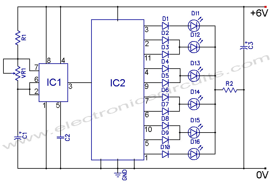
4017 LED Knight Rider Running Light Circuit Diagram. In this 4017 Knight Rider circuit, the 555 timer is configured as an oscillator. It can be adjusted to produce a variety of timing intervals. The 4017 LED Knight Rider circuit utilizes...

A circuit is needed to drive three or more LEDs at a current of 200-350mA each, with the capability to randomly flash or strobe them at a frequency of 5-20Hz. The input power should be low-voltage DC, with a...
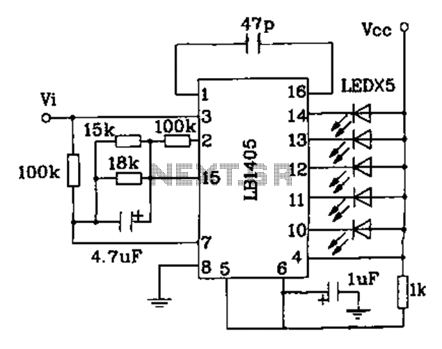
The LB140 is depicted in Figure as a typical driver IC circuit for a five-digit LED level indicator. The BL1405 is commonly utilized in tape recorders for level indication. The LB140 integrated circuit serves as a driver for five-digit LED...
This is a discrete high-current switch-mode LED driver circuit. The fundamental principle of this circuit is based on the buck-converter topology. The efficiency of this circuit is 80%. The discrete high-current switch-mode LED driver circuit utilizes a buck converter configuration...
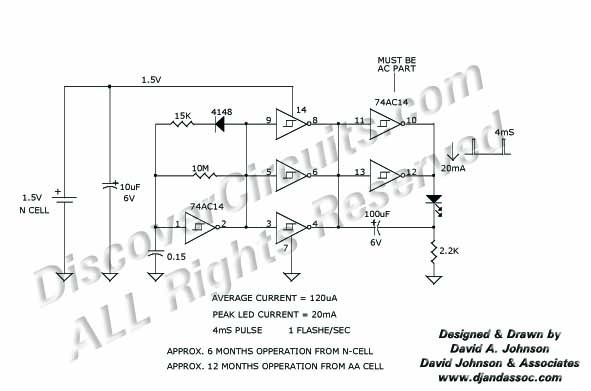
Many published circuits that flash LEDs require 3 volts or more. This circuit utilizes a single inexpensive C-MOS IC and can flash an LED for an entire year on a single 1.5-volt AA alkaline battery cell. The circuit employs...