
Home Built Laser Projector
The laser controller must produce two vector signals (±1V analog) for the galvos, along with a blanking signal (TTL) to modulate the laser output. These signals can be generated using any microcontroller board available or a simple D/A adapter connected to a PC's parallel port. In this project, a new controller board was designed and built to minimize board size. The block diagram for the controller board is illustrated in Figure 7, with the circuit diagram available in the technical notes. The controller is limited to generating vector data with stored frames and does not provide additional control. A comprehensive understanding of the controller board and its firmware is necessary for those intending to build galvos, as the graphic data utilized in laser projectors is vector-based rather than raster-based, making generic graphic tools unsuitable for frame data creation. Specialized vector graphic tools for laser creation can be prohibitively expensive for hobbyists or temporary projects; therefore, a simple vector tracing tool was developed. This tool processes frame files in a generic CSV format to allow for broader usability. The tool is available as freeware in the technical notes, and a script to convert ILD frame files into CSV files is also included.
The servo amplifier circuit is designed to effectively manage the dual functionality of power amplification and signal processing. The integration of both amplifiers on the same board requires careful layout to mitigate potential issues such as crosstalk and feedback loops that could destabilize the system. The choice of components, particularly the operational amplifier, is crucial; the LM675 is suitable for moderate power applications, but its limitations at higher currents necessitate consideration of alternatives like the LM12, which offers greater power handling but comes with the risk of overheating and damaging the galvo coil if not properly managed.
The power supply design is flexible, allowing for either a regulated or unregulated source. The dual-output requirement of ±20 volts can be achieved through various methods, including switching regulators or traditional linear supplies. The design should ensure sufficient current capacity to handle the peak demands of the servo amplifier, particularly during dynamic operation where rapid changes in load can cause significant voltage dips.
The laser controller's capability to generate the necessary vector signals is essential for precise control of the galvos. The use of a microcontroller or D/A converter simplifies the interface between the control logic and the galvo motors, enabling real-time adjustments to the laser output. The development of a custom controller board reflects a commitment to optimizing performance while minimizing physical space, a critical consideration in compact laser systems.
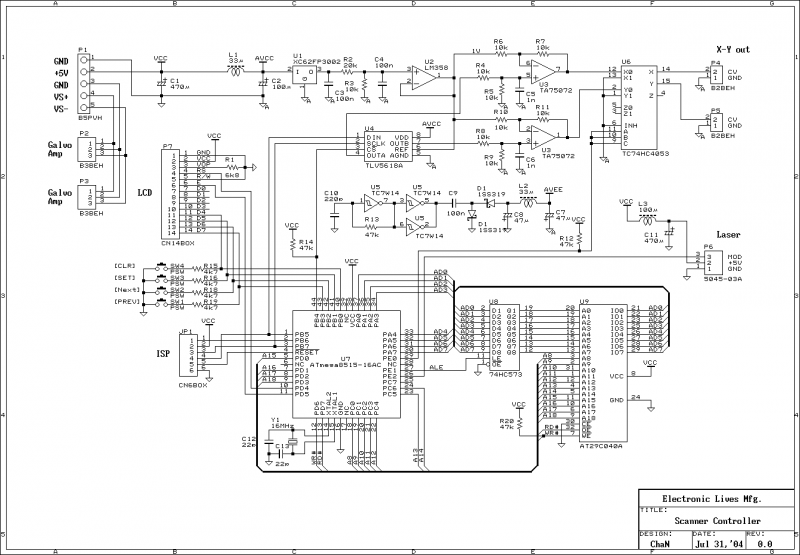
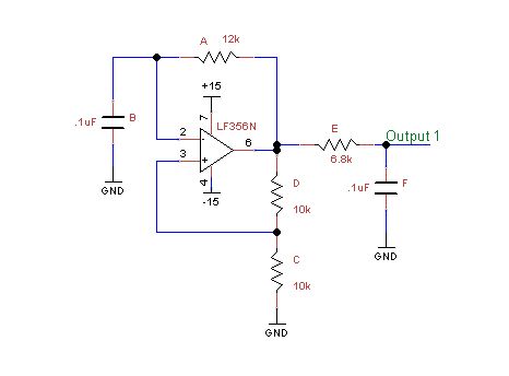
The emphasis on vector graphics for laser applications highlights the need for specialized software tools that can convert artistic designs into a format compatible with laser projectors. The availability of a freeware vector tracing tool enhances accessibility for hobbyists and developers, fostering innovation in laser display technology. The inclusion of conversion scripts further streamlines the workflow, making it easier to integrate various design formats into laser-compatible outputs.This is the built servo amplifier and circuit diagram. This is a simple and ordinary op-amp circuit, there is nothing difficult. However it has power amplifier and small signal amplifier on the board together. You have to pay attention to unintentional coupling on board design otherwise you will be afflicted with oscillation, distortion or instability, and the servo gain will be limited. Currently the PD circuit is a little affected by power amplifier, it may be better to move it on the galvo like existing galvos.
The servo amplifier requires a dual output power supply of ±20 volts. It is generated with a simple DC-DC converter powered from a single +12 volts DC supply. It is not that must be regulated, a traditional transformer-bridge-capacitor type power supply will also work well. This is a wave form which is a step response of the servo amplifier. It must be current controlled however the output voltage is saturating due to coil inductance. The supply voltage should be high as possible to minimize this effect. The voltage dip at high output current also be found. It is due to a current limiting of the LM675, a high power opamp, such as LM12, might be better than LM675.
However such the strong opamp can burn the galvo coil with over load or oscillation so that any thermal protection will be needed to the galvo. The laser controller must generate two vector signals (±1V analog) for galvos and a blanking signal (TTL) to modulate laser output, al least. These signals will able to be generated by any microcontroller board found in junk box or a simple D/A adapter attached to PC's parallel port.
In this project, I designed and built a new controller board to minimize the board size. Figure 7 shows the block diagram for the controller board, and the circuit diagram is available in tech notes. The controller only generates vector data with stored frame and there is no more control. It will not needed to explain each function of the controller board and its firmware because you must have a skill to design a laser display controller if you are going to build galvos.
Because the graphic data used in laser projector is vector based, not rastar based, generic graphic tools cannot be used to create frame data. Any vector based graphic tool is needed to create vector frames. There are some laser creation tools specified for vector graphics, but they are too expensive for hobby use or temporary project, so I developed a simple vector tracing tool.
It handles the frame files in generic csv format because I also wish to use it for any other purpose :-). This is a freeware and is available in tech notes. A script to convert ild frame file into csv file is included too. 🔗 External reference
Related Circuits
Above is the schematic of an oscillator circuit. In technical terms, the oscillator is a Schmitt trigger relaxation oscillator. The Schmitt trigger relaxation oscillator is a type of electronic oscillator that generates a periodic waveform, typically a square wave,...
A tachometer can be constructed using the TC9400 in frequency-to-voltage (F/V) mode to convert frequency information (RPM) into a linearly proportional voltage. This voltage can then be compared to one of several comparators (in this example, using eight). The...
This chapter presents detailed schematics for various power supplies compatible with commonly available Ar/Kr ion tubes in the surplus market. It includes examples of commercial designs such as the Omnichrome 150R and 532 head, Lexel 88 and head, alongside...
A microcontroller operates using digital language, while the inputs it receives from the environment are predominantly analog, meaning they change continuously over time. To enable the microcontroller to interpret these inputs, an Analog to Digital Converter (ADC) is utilized....
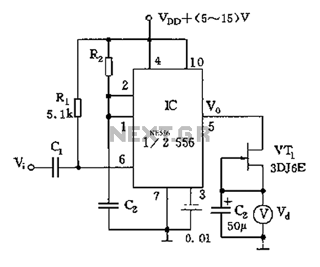
The circuit utilizes switch contacts that are proportional to the speed pulse signal Vi. A differential signal is fed into the trigger side of an integrated circuit (IC), specifically a 555 timer configured in monostable mode (1/2 556), to...
The circuit is divided into two sections: the isolated external loop connected to the remote interface connector on the front of the power supply unit (PSU) and the non-isolated inner loop connected to the high-tension (AC line) supply. The...
Warning: include(partials/cookie-banner.php): Failed to open stream: Permission denied in /var/www/html/nextgr/view-circuit.php on line 713
Warning: include(): Failed opening 'partials/cookie-banner.php' for inclusion (include_path='.:/usr/share/php') in /var/www/html/nextgr/view-circuit.php on line 713