
how to make simple earthquake sensor
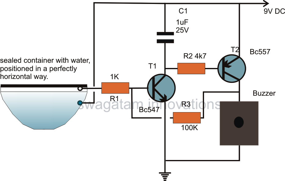
The circuit design utilizes a water-based sensing mechanism to detect swaying motions indicative of seismic activity. The key components include a conductive positive supply immersed in water and a hot end positioned above the water surface. This configuration allows for the detection of changes in water conductivity caused by tremors. When an earthquake occurs, the resulting swaying motion causes the water to create a conductive path between the submerged positive supply and the hot end of the circuit. This triggers the circuit, which can be designed to activate an alarm or indicator to warn of potential seismic activity.
The sensitivity of the circuit can be adjusted by modifying the distance between the hot end and the water surface, as well as by selecting appropriate electronic components such as resistors and capacitors that define the circuit's response time. Additionally, the use of a microcontroller can enhance the functionality of the circuit by allowing for data logging and analysis of seismic events over time. This design is particularly advantageous as it minimizes false triggers from environmental noise, focusing solely on the specific swaying motion associated with earthquake tremors. Overall, this innovative approach provides a reliable and effective means of detecting seismic activity, contributing to safety and preparedness in earthquake-prone regions.The article shows a circuit idea which incorporates an innovative way of detecting the minutest of shocks caused by a possible earthquake tremor. The circuit is so sensitive that it is able to detect tremor of 4 on the Richter scale, yet remains unaffected to loud sounds or irrelevant bangs or noises.
I have seen a number of different circuits of seismic sensors on the net, however most of these have utilized a piezo transducer as the sensor element, God knows how a piezo would detect earthquake tremors. Of course a piezo would detect tremors only if it were used in the form of a load-cell, by integrating some kind of load, assembled for implementing an oscillating action during tremors.
I could have used an LED/LDR arrangement for detecting these ripples, however since we are not interested in sensing vibrations rather only swaying actions, I made a little out of the way approach. Through a few of my previous posts I have already discussed water level sensor circuits where the water`s conducting property is well exploited for the purpose.
The positive supply from the circuit is dipped inside the water while the hot end of the input is placed in such a way that it stands just a mm above the water. The positive of the supply immersed in the water instantly makes contact with the HOT end of the circuit via the water, the circuit gets triggered and immediately latches.
🔗 External reference
Related Circuits
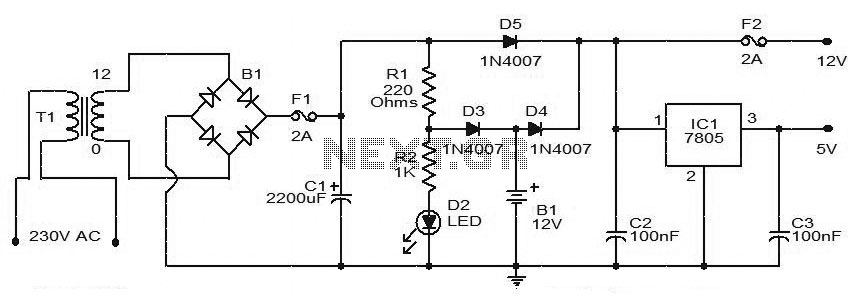
This circuit diagram represents a simple Uninterruptible Power Supply (UPS) capable of delivering 12V unregulated and 5V regulated DC output. The transformer T1 reduces the mains voltage to 12V AC, which is then rectified by bridge B1. The rectified...
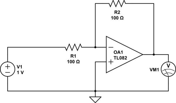
Considering a simple circuit as illustrated below, when the voltage source activates suddenly (changing from 0V to 1V), current will flow through the resistor R1. Assuming an ideal operational amplifier (op-amp) that draws no current, and an ideal voltmeter...
When this circuit is connected to a filter and an oscilloscope, the oscilloscope displays the filter's frequency response. A frequency that sweeps from low to high is applied to a filter. The oscilloscope is triggered by the start of...
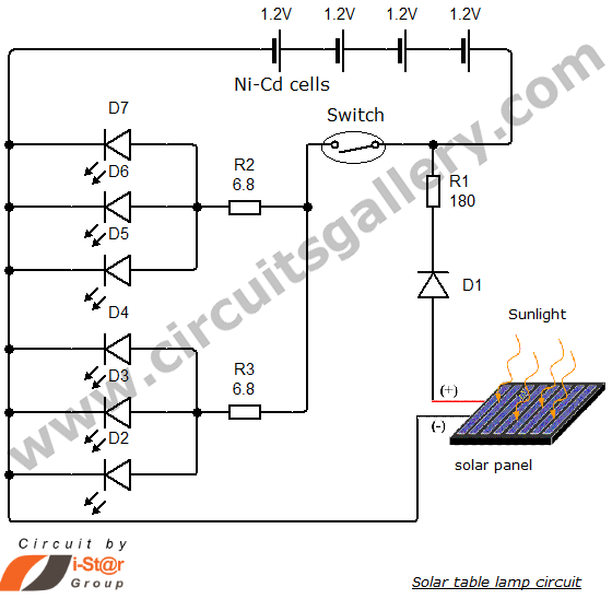
Solar energy has become a popular alternative for electricity production. This project focuses on teaching school students how to create solar lamps for their homes. The primary components of this simple solar lamp circuit include a small solar panel...
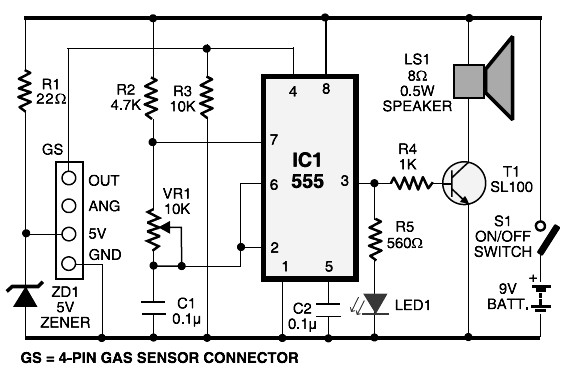
This schematic diagram represents an LPG gas leakage sensor alarm circuit powered by a 9V PP3 battery. A Zener diode (ZD1) is utilized to convert the 9V input into 5V DC, which is required to operate the gas sensor...
In designing a logic circuit, it is often necessary to compare the values of two digital data inputs. Creating a custom magnitude comparator can lead to increased use of logic integrated circuits (ICs), as well as greater time and...