
How to properly snub transient spikes from a transformer and prevent switch mode power supply burn out
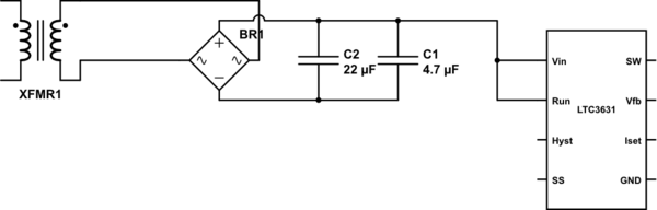
The described circuit involves a transformer with long leads that may introduce inductive effects and voltage spikes due to frequent switching on the primary side. The LTC3631, a step-down DC-DC converter, exhibits a failure marked by a blowout, likely caused by voltage transients exceeding its rated input protection. The presence of a voltage reading of 28Vac indicates the potential for over-voltage conditions, especially when rectified to a DC level close to the LTC3631's maximum rating of 60V.
To mitigate potential voltage spikes, several protective components can be integrated into the design. The use of Metal Oxide Varistors (MOVs) across the primary side can effectively clamp high voltage transients, preventing them from propagating into the transformer and downstream circuitry. A series resistor can further limit the energy of surges while maintaining efficiency, given the low current draw of the regulator.
On the secondary side, implementing a Transient Voltage Suppressor (TVS) diode in parallel with the LTC3631 provides an additional layer of protection. This configuration allows the TVS to divert excess voltage away from the chip during transient events, while a series resistor helps manage the current flowing through the TVS, minimizing power losses.
The design should also incorporate local bypass capacitors placed as close as possible to the Vin and Run pins of the LTC3631 to stabilize the input voltage and filter out noise. The addition of reverse-biased diodes on these pins can prevent negative voltage excursions that could damage the IC. Furthermore, a negative clamp diode at the SW node is advisable to protect against negative voltage spikes that may occur during switching events.
Overall, careful consideration of component placement and selection in the schematic can enhance the reliability of the circuit and prolong the lifespan of the LTC3631, ensuring stable operation even under potentially adverse conditions.The leads from the transformer to the circuit are quite long (>5m). Apparently the 110V side of the transformer was switched off somewhat frequently lately which likely caused a spike on the secondary (24V) side. The input pin of the LTC3631 has a visible mark where the blowout occured (gas escaped). The LTC3631 is protected upto 60V on it`s power -in. I doubt that the failure is due to an over-voltage situation. Maybe it might be better to sit-back and wait for reasons without 2nd-guessing the possible cause. Hey it could be exactly what you say but, there may be other factors you haven`t mentioned that makes you sure it is this. This info would be needed to give a decent answer to your question. Andy aka Apr 5 `13 at 20:32 @Andyaka the only other information I have is that I read a little over 28Vac from the transformer which translates to 39.
5Vdc just below chip`s normal tolerance. It`s possible that it was being too close to it`s normal limit. I`m not sure if that would cause the physical blowout. The chip is not overloaded and runs quite cool normally. MandoMando Apr 5 `13 at 20:58 @dext0rb no, I haven`t seen any spikes, just a blown chip. The handheld meter reads the input at about 28Vac. It was installed last week, so didn`t live long at this location regardless. MandoMando Apr 5 `13 at 21:01 The easy solution is adding some clamping on the primary side of the transformer to limit any surge energy coming in - a MOV from line to line will shunt any high voltage energy away from the transformer. A small series resistance would also help limit the surge energy, and wouldn`t be excessively lossy since the regulator draws such a low current.
Safety-rated X-capacitors from line to line may also help with smaller surges (also sometimes called `fast transients`) - just don`t forget to put a resistor in parallel with them that would discharge them within 30 seconds, for safety reasons. Clamping also works on the secondary side. You could add a small resistor in the positive feed to the regulator, then put a TVS in parallel with the regulator (between the positive feed and ground).
The TVS would clamp the voltage to a safe level and the resistor would limit the TVS current. Again, it would burn some power all the time, but the regulator isn`t high-power so the losses should be manageable. Local capacitors directly at Vin and Run going directly to the IC ground are essential. You could also consider adding reverse biased (negative clamping) diodes on these pins (to prevent them from somehow going below GND).
A negative clamp diode at the SW node can be helpful too. 🔗 External reference
Related Circuits
The circuit is designed for individuals who spend extensive hours exploring the various resources of this site. Although it comprises only three components, it effectively indicates whether the telephone line has been released after a prolonged connection via modem...
Feedback in a public address amplifier should be avoided. The ideal solution is to adjust the positions of the microphone and speaker; however, this is not always feasible in many situations. A frequency shifter that alters the output frequency...
This dual polarity power supply is easy to build, requires few parts, and is adjustable from 0-15 volts. It is great for powering op amp circuits, as well as other circuits that require a dual supply voltage. The described dual...
This circuit utilizes a 74HC14 hex Schmitt trigger inverter as a square wave oscillator to drive a small signal transistor configured in a class C amplifier. The oscillator frequency can be set to a fixed value using a crystal...
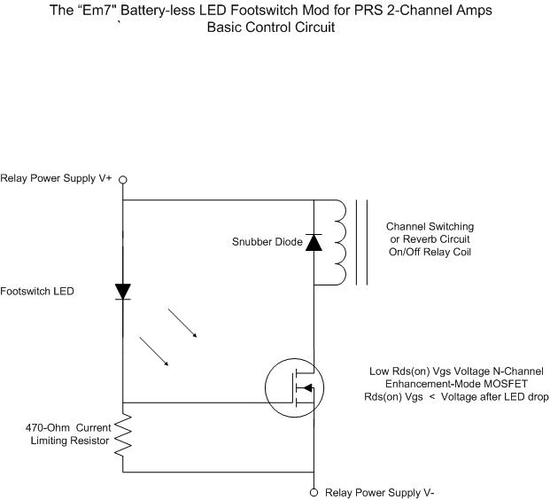
For individuals seeking LED-based footswitching without the inconvenience of battery installation, a battery-less LED-based footswitch modification is being developed for 2-channel amplifiers. This solution is designed to work with the existing TRS jack and footswitch, and it will involve...
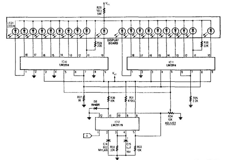
The analog display includes a frequency-to-voltage converter (IC12) along with bar-graph segment drivers IC10 and IC11. The calibration adjustment resistor R34 is configured to ensure that an engine RPM of 5,000 to 7,000 activates the first LED, which indicates...
Warning: include(partials/cookie-banner.php): Failed to open stream: Permission denied in /var/www/html/nextgr/view-circuit.php on line 713
Warning: include(): Failed opening 'partials/cookie-banner.php' for inclusion (include_path='.:/usr/share/php') in /var/www/html/nextgr/view-circuit.php on line 713