
HOW TO READ CIRCUIT DIAGRAMS
The process of reading circuit diagrams involves understanding the symbols and connections that represent electronic components and their interrelations. Key components include resistors, capacitors, diodes, transistors, and integrated circuits, each represented by standardized symbols. Familiarity with these symbols is essential for accurately interpreting the function and layout of a circuit.
Once the circuit diagram is understood, the next step involves assembling the circuit on a breadboard. A breadboard is a reusable platform that allows for the easy construction of electronic circuits without soldering. It consists of a grid of holes that facilitate the insertion of components and jumper wires, enabling quick modifications and troubleshooting.
To begin assembling a circuit on a breadboard, the first step is to identify the power supply requirements, ensuring that the correct voltage and current ratings are adhered to. Next, components should be placed on the breadboard according to the schematic, ensuring that the connections align with the intended design. It is crucial to maintain proper polarity, especially for polarized components such as electrolytic capacitors and diodes.
After placing the components, jumper wires can be used to connect them according to the circuit diagram. It is advisable to follow a systematic approach, connecting one section of the circuit at a time to minimize errors. Once the assembly is complete, the circuit can be powered on for testing.
Throughout the process, verification of connections is essential to ensure functionality. If the circuit does not operate as expected, troubleshooting steps should be undertaken, such as checking for loose connections or incorrect component placements. This hands-on experience is invaluable for understanding electronic principles and developing practical skills in circuit design and assembly.this instructable will show you exactly how to read all those confusing circuit diagrams and then how to assemble the circuits on a breadboard!for all.. 🔗 External reference
Related Circuits

Power Amplifier Speaker Protection Circuit Schematic. When a power amplifier is switched on, a loud thump sound is often heard due to a sudden heavy discharge. The power amplifier speaker protection circuit is designed to prevent loud thump sounds during...
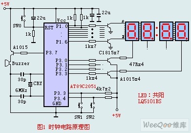
The circuit design incorporates an anodic Nixie tube for the LED display. It utilizes the LQ5101BS general luminous diode, with the driving transistor being either the 2SA1015 or 2SC1815 types, which are readily available. Additionally, low-power transistors such as...
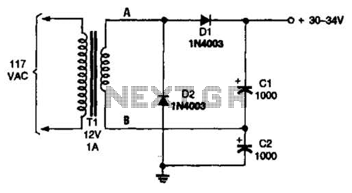
The voltage doubler consists of two diodes (D1 and D2) and two capacitors (C1 and C2), which are supplied by a 12-V, 1-A step-down transformer (T1). The voltage doubler circuit is designed to convert a lower input voltage into a...
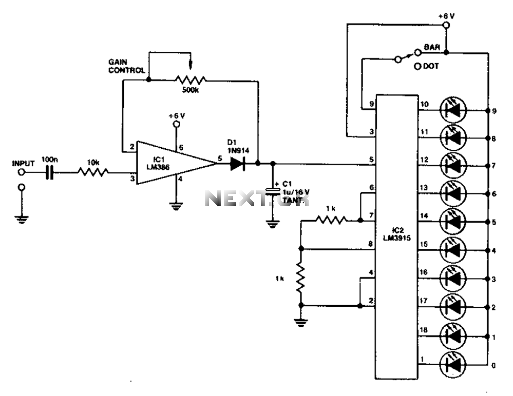
A simple level power meter designed to provide a high-fidelity sound system with a bar or dot matrix display. The green LED display indicates levels from 0 to 7; level 8 is shown in yellow, and level 9 is...
120V galvanic acupuncture salmon RI. The system features a wind-down rectification and a limit irrigation mechanism to achieve an amplitude of 24V. It includes isolation diodes and a steady stream over the circuit. The design ensures that a voltage...

This circuit diagram of a digital clock utilizes six common anode seven-segment displays to indicate the time. It does not require microcontrollers or PICs for operation. The circuit operates using the MM5314 integrated circuit, functioning at either 50 Hz...
Warning: include(partials/cookie-banner.php): Failed to open stream: Permission denied in /var/www/html/nextgr/view-circuit.php on line 713
Warning: include(): Failed opening 'partials/cookie-banner.php' for inclusion (include_path='.:/usr/share/php') in /var/www/html/nextgr/view-circuit.php on line 713