
how to use in-built adc of avr
The Atmega16 microcontroller's ADC system is critical for interfacing with analog signals, allowing for the conversion and processing of real-world data. The ADC operates by sampling the input voltage at the AREF pin, which establishes the upper limit of the analog input range. The resolution of the ADC is determined by the reference voltage; thus, it is essential to ensure that AREF is set appropriately to achieve the desired accuracy in conversions.
The AVCC pin must be connected to the microcontroller's supply voltage to ensure proper functionality of the ADC and PORTA. This connection is vital for the stability of the ADC operation, as fluctuations in supply voltage can lead to inaccurate readings. The ceramic capacitor between AVcc and AREF serves to filter out noise and stabilize the reference voltage, enhancing the performance of the ADC.
When designing circuits that utilize the Atmega16's ADC, it is crucial to consider the layout and grounding to minimize interference that could affect the analog signals. The common pins used for ADC inputs should be carefully managed to avoid crosstalk and ensure reliable performance. Proper decoupling capacitors should also be employed near the supply pins to maintain a clean power supply to the microcontroller and its peripherals. Overall, the integration of the ADC with the Atmega16 microcontroller allows for effective data acquisition and processing in various applications, including sensor interfacing and control systems.Microcontroller understands only digital language. However, the inputs available from the environment to the microcontroller are mostly analog in nature, i. e. , they vary continuously with time. In order to understand the inputs by the digital processor, a device called Analog to Digital Converter (ADC) is used.
As the name suggests this peripheral gathers the analog information supplied from the environment and converts it to the controller understandable digital format, microcontroller then processes the information and provides the desired result at the output end. ADC channels in Atmega16 are multiplexed with PORTA and use the common pins (pin33 to pin40) with PORTA.
ADC system of Atmega16 microcontroller consists of following pins: ii. AREF: Pin32 of Atmega16 microcontroller, the voltage on AREF pin acts as the reference voltage for ADC conversion, reference voltage is always less than or equal to the supply voltage, i. e. , Vcc. iii. AVCC: Pin30, this pin is the supply voltage pin for using PORTA and the ADC; AVCC pin must be connected to Vcc (microcontroller supply voltage) to use PORTA and ADC.
Connect the circuit as shown in the circuit diagram. A ceramic capacitor 104 is connected in between AVcc (pin 30) and Aref (pin 32). AVcc (pin 30) is connected to external supply +5V. 🔗 External reference
Related Circuits
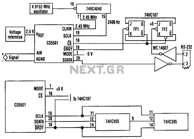
The CS5501 16-bit delta-sigma analog-to-digital converter continuously converts signals, outputting conversion words to its output register every 1024 cycles of its master clock, as it lacks a start convert command. By integrating a standard dual J-K flip-flop into the...
The following article is a continuation of the application note titled "Defining and Testing Dynamic Parameters in High-Speed ADCs, Part 1." It outlines the test conditions and setup recommendations necessary for effectively measuring the dynamic performance parameters of high-speed...
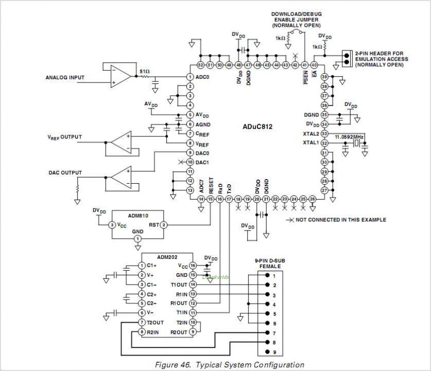
The ADUC814 MicroConverter is a fully integrated 12-bit data acquisition system-on-a-chip. Like all of ADI's MicroConverter products, it features precision A/D and D/A conversion along with a Flash Microcontroller on a single chip. The ADUC814 MicroConverter is designed to streamline...
Ready-made programmers are available for purchase, but it is possible to create one using spare parts. The simple SI-Prog requires minimal components and is compatible with various software. The complete SI-Prog is designed to program different chip types and...
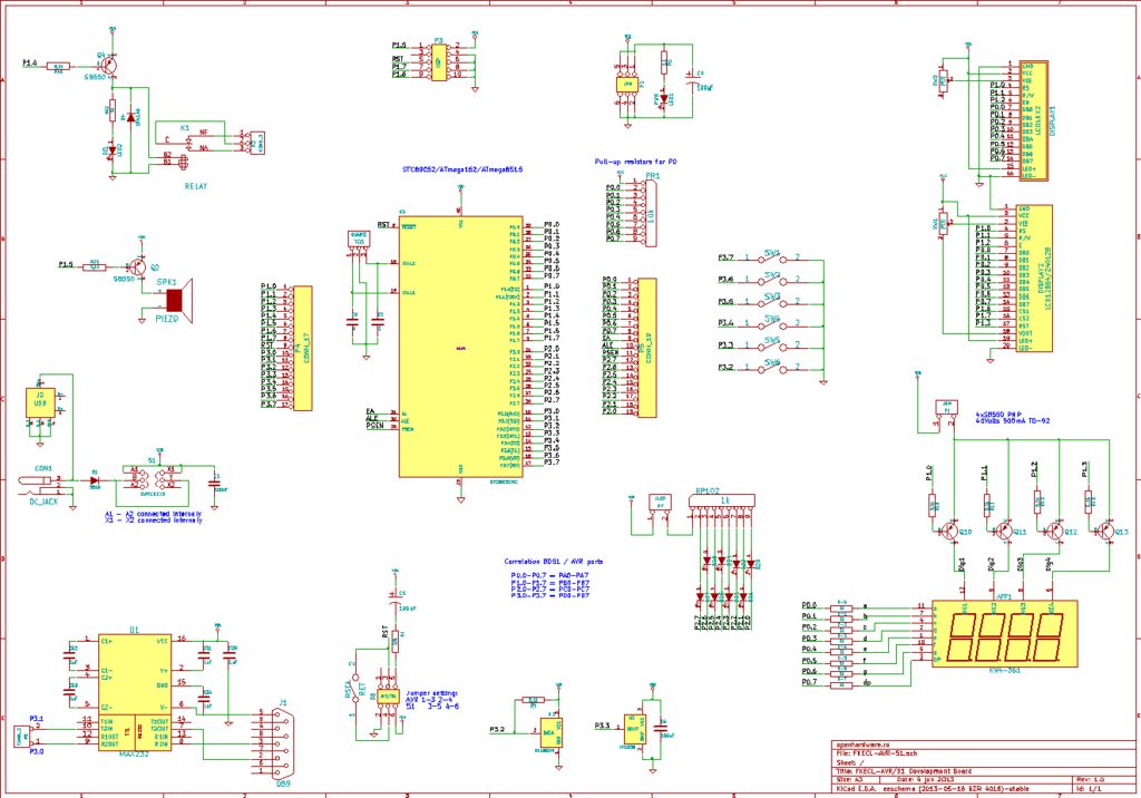
A circuit diagram was created using KiCad, which is considered an excellent free software for designing electronic diagrams and printed circuit boards. KiCad is a powerful open-source software suite that allows engineers and hobbyists to design electronic circuits and...
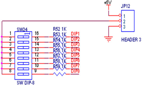
A switch is an electrical component that can break an electrical circuit, interrupting the current or diverting it from one conductor to another. A switch may be directly manipulated by a human as a control signal to a system...